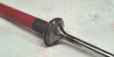
In the last pic, the joystick was holding on to an intake valve, which has a larger diameter head than the suction cup diameter. This pic shows the joystick on an exhaust valve: the suction cup is a tad larger than the valve head...no problem.
Look closely, and you will see the grey lapping compound around the valve seating face surface. That's where we want it to be. When the joystick and valve are then inserted into the cylinder head in the valve guide for that valve, the compound will be between the valve face and the valve seat face in the head.