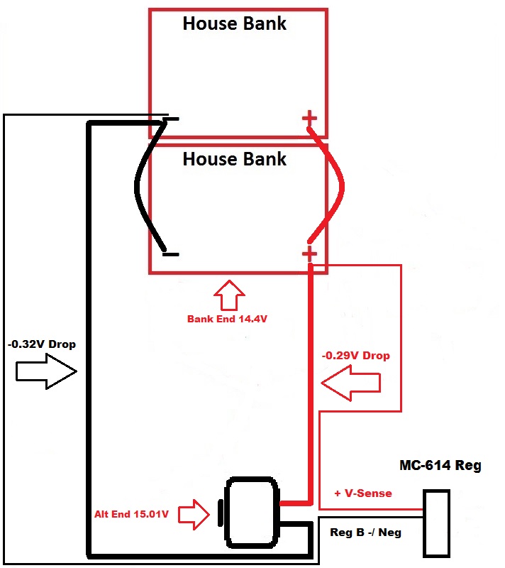
Finally we now have correct voltage sense wiring. As can be seen the regulator is now driving the alternator to 15.01V in order to have 14.4V at the battery end. The voltage sensing circuit on Balmar and the Xantrex XAR regulators is a CIRCUIT. This means the red wire and the regulator negative wire both need to see battery terminal voltage for optimal performance.
NOTE: In the spirit of simplicity of the illustration these drawings lack an alternator output fuse. This fuse would be within 7" of the battery banks positive terminal. They also lack a positive volt sense wire fuse, also within 7" of the battery banks positive terminal...
Get all the speed & charge performance you've paid for by wiring your alternator positive & negative output direct to the house bank. After you've done that wire the volt sensing circuit direct to the positive and negative bank terminals as well. Like anything it's all in the little details..