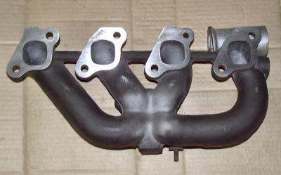
With the four flanges tied together with iron bridges, the flanges do not spread out like the old style manifold flanges commonly do. This tied casting is a marked improved design.
While the flanges do not spread, they can and do warp. The warping does contribute to gasket failure; and I am convinced that the flange warping also contributes to the cracking of the manifold in the goilet area.
I resurface the flanges to restore flatness on the same plane. That removes any stress when the manifold is bolted down on the head. I also match the ports' opening to the gasket and the head; to provide a step up in size. This removes any barrier to good flow from the head into the manifold runners.
The manifold does not fit down on the head exhaust port studs tightly. The manifold is "located" only at one stud: the upper stud at number 3 cylinder. All other stud holes on the manifold are oversize to allow for expansion and contraction during running and cool down after shut down. I verify where to sit the manifold on the studs before tightening the manifold down to ensure that the flange openings are aligned to the exhaust ports from the head.
Since the manifold can 'float' up or down against the head, which can lead to misalignment of the openings; it is important to make sure that there is no outside forces applied to the manifold to cause it to float up or down. Such forces on the manifold causing it to shift come from the down pipe and the exhaust system. As I illustrate the new 3in stainless steel exhaust system install, I will show what I do to counteract and eliminate those forces on the manifold.
The area of the goilet shows where I did some sandblasting to see if there are any cracks; or how extensive the cracking is. This manifold does have two cracks in the goilet; and can be seen in earlier pics of the plenum porting. I have only seen a couple of these manifolds that were not cracked at all. Most of the ones that I have seen are similar to this one: a couple of cracks in the goilet area.
Why the manifolds crack is rather obvious: they get really hot.
But there is more to it than that, because the cracks usually occur in the same places. I am satisfied that the restrictive opening of the outlet is part of the reason: too much heat is retained by the flow restriction. The very thick outlet flange, in comparison to the thickness of the individual runners also contributes to the cracking. The warping flanges is another of my suspects.
By improving the flow through the manifold, the turbo, and the rest of the exhaust system; and by restoring flange flatness, I have been able to reduce the retained heat load on the manifold; and the stresses due to warped flanges.
The manifolds still get really hot; but the amount of cherry red glow that I have observed on stock manifolds, with stock turbos, and stock exhaust systems, is greatly reduced after I do my work.
Reducing the retained heat loads extends the service life of the system components...and definitely improves the performance.