


|
|
|
|
|
|
| Paul Meskill | profile | all galleries >> Galleries >> Olympus c-2100uz MODE DIAL "DIY" REPLACEMENT | tree view | thumbnails | slideshow |
 Prior to disassembly. | This is the way the camera came to me.
Note! The top of the Mode Dial is missing. it was lost at the time of the accident that caused this damage. Later pictures show the damage to the Mode/Switch assembly. |
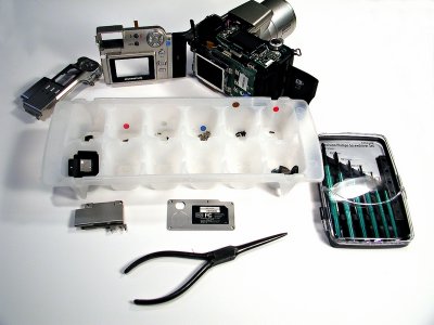 My Setup for the UZI Mode Dial Knob Repair | I used an old ice-cube tray to hold the different screws. See the little colored dots in the different compartments.These dots are also on the camera as I removed the screws. The screws are all the same diameter but are in different lengths.There are silver color ones and black color ones. There are (3) different lengths of the silver ones with a total of (17). The black screws there are (3) different lengths for a total of (9) screws. Some of the screws are machine screw thread and some are self thread for plastic so keep them sorted out. I used a 2mm Phillips driver and the long fine nose plier was used to dis-connect the cables.There are two cables to dis-connect. One at the Mode Dial assembly and one from the back of the camera |
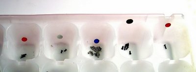 Parts Tray. | A corner of the ice cube tray.
You can see the color dots better in this photo. |
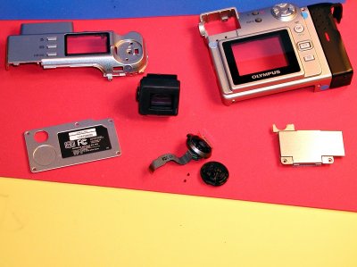 Removed outer parts. | This is what I took off.
Maybe too much? Found the two broken rivets laying in the case from the destroyed Mode/Switch knob. In this picture is the Top, Back, the EyePiece, the ID plate from the bottom of the camera and the left side cover door. The mangled part is the remains of the old Mode Dial. |
 Eye piece | This is held with two screws and was the first part I took off.
Plan on doing a cleaning prior to the re-assembly. |
 Left Side with door removed. | I think this was the next part I removed. ( the cover door) This is held with three screws.
Not shown in this photo, is the ID plate on the bottom of the camera. Held with four screws. As a added note, loosen the small black knob over the flash port to remove the back and this door. |
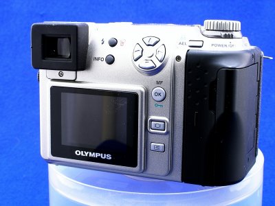
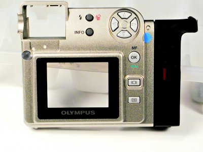 Camera Back. | If you have all the screws removed the back should
come right off.Do not pry. I also unpluged the ribbon cable from the circuit board as I did not wish to break any wires etc. in handeling. In this picture, you can see some of my little colored dots so that I can try and get all the screws back in their right spots. |
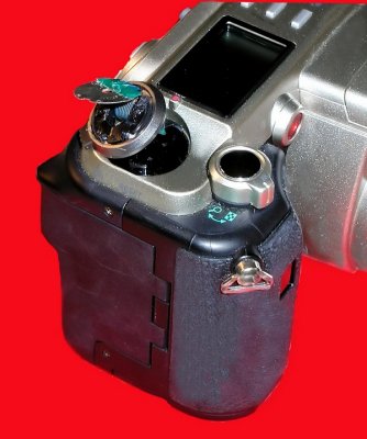
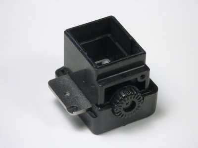
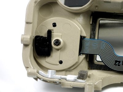
 Top cover | Note the shape of the recess for the Mode/Switch Knob.
This Knob assembly is held in place with a screw in the center plus a special black color plastic clip. The next picture shows this clip. This clip is installed from the underside of this cover at the little rectangle hole. The other slot to the left of the recess is for the cable. Hard to see in this photo, but the AEL button shows. This is held in place with a screw. If you took it off like I did put it back on. |
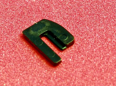 Retaining Clip Mode Dial. | See previous picture. This clip is to help retain the Mode Dial. |
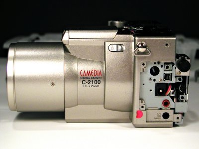
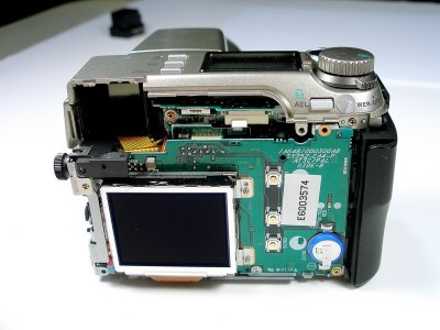
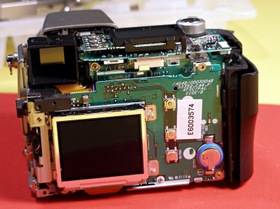 UZI with covers off. | This is a reference picture for later?
Note the connector just to the right of the screw head.and almost to the top of the camera. (circuit board) This is the connector for the cable that is on the back cover. |
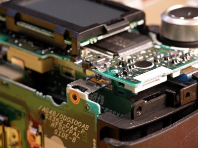 Top right. | Note under the white panel on the circuit board
is the connector for the ribbon cable from the Mode/Switch Knob. |
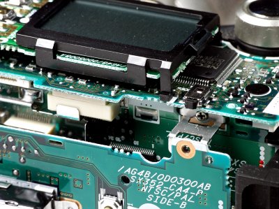
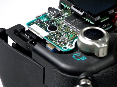 Top Right Mode Dial Area | You can see the connect (white) for the Mode Dial Cable
The other cable shown is for the Zoom Knob? Now if you have to replace the Zoom Knob, remove the hand grip cover(two screws on the face near the lens) Then you will see the screws for the Zoom Knob. Remove one screw from the corner of the circuit board to help with routing the ribbon cable. |
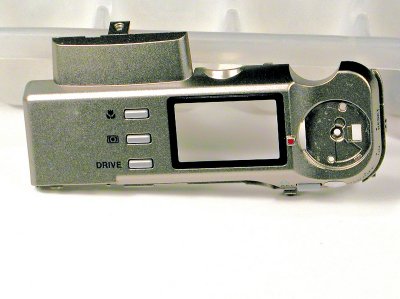
 Close-up Back of Camera | About in the middle of the picture (top/bottom)
and on the far left is the connect point for the cable to the back of the camera. |
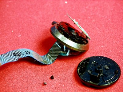 Broken Mode Dial | What ever hit this knob broke the top completely off.
The fellow that I bought the camera from told me he could not find it. I did find two of the little rivets used to hold the assembly together. They were on top of the circuit board. I think there are supposed to be four rivets? The other two must have fallen off since the accident. |
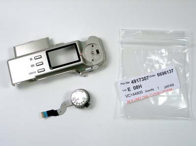 New Mode Dial | Received the new Mode Dial from Olympus Parts.
Ready to mount it to the Top Cover. |
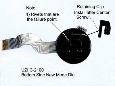 Mode Dial Notes | The failure point for all the Mode Dials
that show that Mode Dial "dangle". is at the (4) very tiny Rivets that hold this assembly together. At least in all that I have seen. So treat your UZI with gentle handling. |
 Mode Dial Asembled to Top Cover. | Note that the Mode Dial assembly is put on to the
cover from the top side, with the ribbon cable thru the slot in the cover. There are two small protrusions and a rectangular block cast on the black plastic bottom of the Mode Dial assembly for orientation. Then put a screw in the center and tighten.Then the plastic "keeper" |
 Top Cover back on. | The Top Cover is the first piece to put
back on to the camera. This can be a lesson in frustration or at least make you wish you had many hands. The first thing that I did was to clean the LCD Top Screen on the camera, then cleaned the inside glass of the top cover. Handle with care after this cleaning "No Fingerprints Allowed". Then it is time to re-attach the ribbon cable to its connector keeping in mind the routing for the cable. Then tilt/wiggle the cover and at this time open the Flash Door and feed the Top Cover tab thru the opening, so that the tab and screw align inside the flash compartment. Handle with care, keep in mind that you do not want to break the ribbon cable or disconnect it. Again keep your fingers off the LCD and the glass. This is the hardest part of the whole assembly, but take your time and you will get there. |
 All back together. | Here is the order I put the camera back together
after the top cover was on. Install the side door that covers the input/output stuff. Remove the little cover cap over the Flash Port and set it aside for a bit. Next I did some more cleaning. The LCD screen and the inside of the glass on the back cover of the camera. Again keep your finger off. Then I plugged the ribbon cable from the back of the camera into its connector. Wiggle the back until you get it back on, it has to tuck in under the cover on the right side and match up with the side door on the opposite (left side) of the camera. I have not mentioned that you should be putting some screw in to hold things. My practice is to never tighten screws until I have things in place. Then I put on the bottom plate and the eye-piece. Hope all of the above is clearer than "Mud". If not give me an Email. |
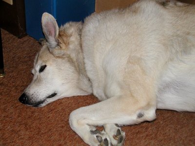
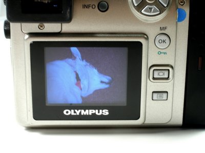 Fired Up. (hard to believe) | Put in (4) 2000ma batteries and a 16mb memory card.
Now how is that for confidence in my work? If it screwed up, I had no desire to wreck a 128mb card. Turned the little tab to on and much to my surprise the camera came alive. My poor dog is still recovering from a hard New Year's eve so I took his picture. One little item I did not mention. At this point with the camera working, I still had three tiny screws left over. As a result I took the back partialy off and found where in my haste to get the back assembled, I had left them off. Now I have no parts left over, the camera works. What more can I ask for? |
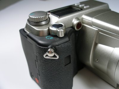
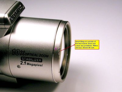 Nose Ding | This is the only mark that I have
found on the camera. It does not effect the operation of the camera in any way. Filters and Aux. lenses fit the way they should. Lens and LCD are clear of scratches. |
 Ashley with the repaired UZI | This and the next picture were taken with
this repaired camera. I am most pleased with how this project turned out. I have checked all the menu items over, the camera seems to be OK as far as focus, both at W and T. I did a pixel re-map, set the time and date. The only mark on the camera is the one shown above which when the filters are on, can hardly be seen. |
 Ashley as a Macro | Again, Ashley is still resting. Some times a soft growl
and also some feet twitch as a result I think of a dream. Hope you enjoyed this gallery, I had fun doing it and the result of being able to put a classic camera back into service again was very rewarding. How about you? Ready to give it a try? |
[ uzi_projects ] |
| comment | share |
| Mike | 22-Jan-2012 14:12 | |
| Albert | 27-Sep-2010 22:08 | |
| Kiriakos - Greece | 29-Jan-2010 21:15 | |
| Kevin | 01-Nov-2008 11:08 | |
| Johnny | 07-Aug-2008 01:12 | |
| John Gardner | 24-Jun-2008 00:26 | |
| Guest | 13-Jan-2007 00:00 | |
| Guest | 04-Jan-2007 19:41 | |
| Pam Brake | 03-Jan-2007 22:49 | |