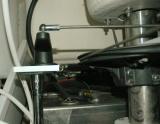
This is the actual RPS and the Starboard base plate which it's mounted to. It's critical to the performance of the Autopilot that the sensor be installed so it's fore / aft orientation is mounted in-line with the center-line of the hull and then bolted down in this position. It does not need to be on the center-line just aligned with it. For this install it was easiest to line up the base and top plates before installing the set screws so I had nice 90 degree angles to work off of. before the RPS is permanently installed you need to ensure the radial drive does not over-steer the RPS stops. If you find you're pushing the limits of the RPS, side to side in relation to its physical range, simply move your pivot point closer to the rudder post. Moving the pivot point towards the rudder post will result in less throw and keep you well within the stop limits of the RPS...
If the radial drives pivot point mounting location can rotate more than the RPS can handle, it will break, plain and simple. Over turning or over throwing the RPS can be remedied by adjusting the rudder stops, to accommodate the RPS, or by simply moving the pivot point closer to the rudder post. The latter is often the easiest.
Installing the threaded connector rod is simple but it will need to be cut to length. Always cut it slightly longer and shorten as needed. Once you cut it too short you can't make it grow.Better to cut twice if you have to rather than ordering another rod because you cut it too short. Never cut short and always err on the large side when test fitting this piece.
Once all the hardware is installed you simply run the RPS data wire to the Autopilot control head and connect it. Depending upon how you mount it you may need to reverse the wires.