My Raymarine autopilot came equipped with a rudder position sensor which aids the course computer in steering a straight course. The problem with these sensors is that it is a servo type device that needs to monitor the rudder quadrant for it's position and must be installed so it can handle the swings of the rudder to a full stop on both the port and starboard turns.
CLICK AN IMAGE FOR A LARGER VIEW
11-MAR-2006
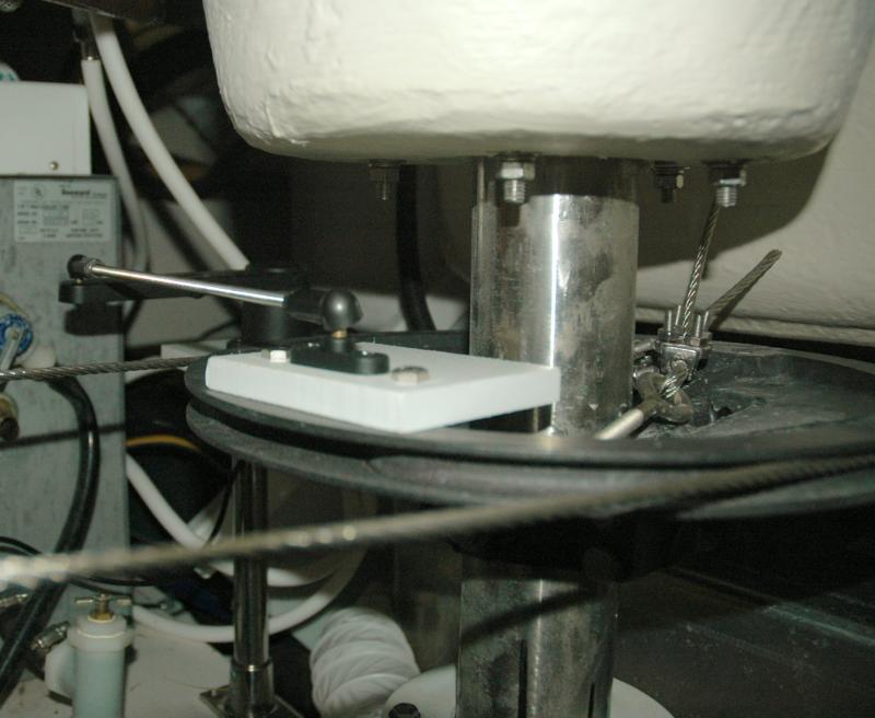
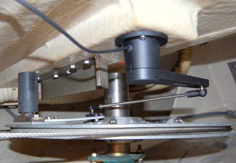
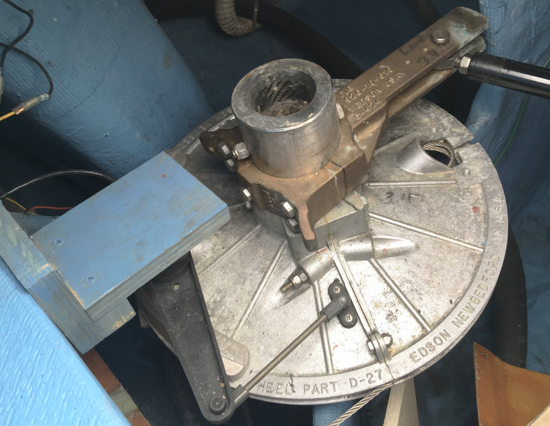
Rudder Position Sensor - Quadrant Close Up
In this picture you can see the steering systems radial drive and the Starboard shim I fabricated to attach the rudder position sensor to.
A rudder position sensor is really just another navigation system transducer. The RPS tells the autopilot course computer where the rudder is at all times. This greatly helps the AP's course computer in holding an accurate course. Over the last ten or so years AP manufacturers have tried very hard to "program out" the RPS by adding rate gyros, prediction & behavior learning software etc. etc. yet with all this technology nothing improves AP performance like a rudder position sensor.
On low end price point autopilots, such as Raymarine's wheel pilot systems, the RPS, which used to be standard equipment, is now optional. In my experience the RPS is not "optional" if you desire the best performance. For coastal cruising you can sneak by without one but your AP performance will always be better with one.
For this particular installation I chose SS tube and Starboard marine lumber. Starboard is a high modulus engineered plastic sheet product available in thicknesses to 3/4 inch. Starboard is impervious to moisture and rot and is very well suited for certain uses on a boat. It works & cuts similarly to wood and is a tremendously useful but very expensive product. For small jobs like this I always save "Starboard" end cuts or waste material from bigger jobs..
On many Edson radial drives, some folks refer to them as "quadrants" but the round ones are technically called radial drives, there are two 5/16 threaded holes already drilled and tapped into its surface for the rudder stop.
I simply measured the hole center to hole center of these 5/16 threaded holes and transferred the measurements to the Starboard shim using a set of calipers. I then drilled the two holes and mounted the ball, which is RPS's ball & socket pivot point to the Starboard perfectly centered between the two 5/16 holes. With the ball mounted, and screwed into the Starboard shim, I then bolted the shim to the quadrant. In the picture you can see the two 5/16 bolt heads with the ball mount for the sensor in between them.
11-MAR-2006
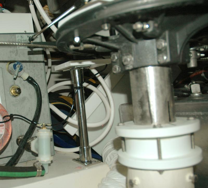
Rudder Position Sensor Base
On this particular Catalina there was already a fiberglass shelf for the water heater. The shelf was perfectly level and very close to the steering quadrant. This was good because I the RPS needed to be on the same plane as the quadrant. All I now needed was to come up with was a mounting bracket. The bracket for the RPS only needed to elevate the sensor, and make it level with the quadrant, but unfortunately you can't just buy a pre-made bracket in that size. Fortunately, because of the water heater shelf, the bracket did not need to be of an odd angle defined by the hulls shape as can often be the case.
After considering the numerous options I decided to make a bracket out of one inch stainless steel rail / dodger tubing and two 90 degree stainless steel deck fittings. I measured for the bracket height by laying a flat edge across the quadrant and measuring from the flat edge to the the water heater shelf. I then subtracted, one half inch of total height, for the Starboard base plate the sensor would eventually be bolted to. While these fittings are costly they were a huge labor savor so in the end it was less costly to use more expensive components than to run up labor costs.
To cut the one inch stainless steel pipe I use a Rigid pipe cutter commonly used for cutting copper pipe. Rigid makes blades specifically for stainless but for just a few cuts the standard blace can work just fine.
Next I needed to attach the deck fittings to the pipe. The fittings come with set screws but I did not fully trust them in this situation. To be sure the deck fittings would not twist under a load I tightened the set screws then removed them leaving a mark on the tubing where I needed to drill two very small holes. I drilled the two holes and then re-installed the set screws. The set screws have a pointed tip and the hole was jut big enough to accept 75% of this tip so they would not allow the deck fittings to twist. I used Loctite on the set screws, when re-installing them, just to make sure they would not back themselves out.
11-MAR-2006
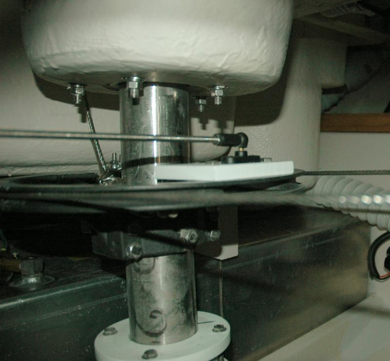
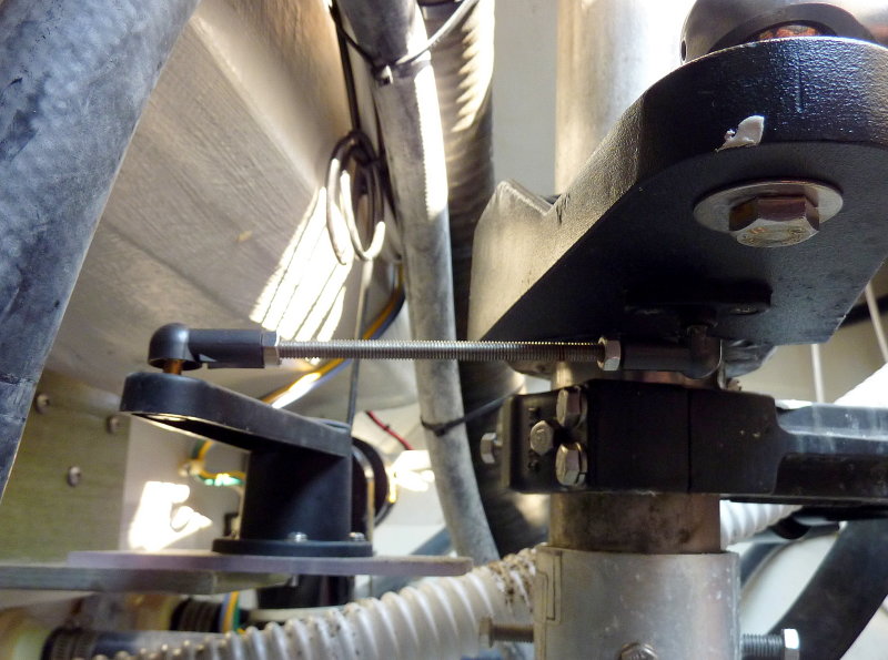
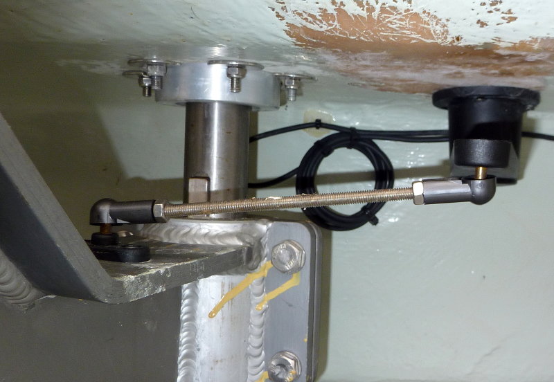
Rudder Position Sensor Quadrant Mount
In this photo you can see the Edson radial drive, shim, the RPS ball & socket & the stainless steel threaded rod connecting the RPS (rudder position sensor) to the radial drive.
11-MAR-2006
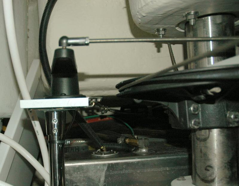
Rudder Position Sensor Top
This is the actual RPS and the Starboard base plate which it's mounted to. It's critical to the performance of the Autopilot that the sensor be installed so it's fore / aft orientation is mounted in-line with the center-line of the hull and then bolted down in this position. It does not need to be on the center-line just aligned with it. For this install it was easiest to line up the base and top plates before installing the set screws so I had nice 90 degree angles to work off of. before the RPS is permanently installed you need to ensure the radial drive does not over-steer the RPS stops. If you find you're pushing the limits of the RPS, side to side in relation to its physical range, simply move your pivot point closer to the rudder post. Moving the pivot point towards the rudder post will result in less throw and keep you well within the stop limits of the RPS...
If the radial drives pivot point mounting location can rotate more than the RPS can handle, it will break, plain and simple. Over turning or over throwing the RPS can be remedied by adjusting the rudder stops, to accommodate the RPS, or by simply moving the pivot point closer to the rudder post. The latter is often the easiest.
Installing the threaded connector rod is simple but it will need to be cut to length. Always cut it slightly longer and shorten as needed. Once you cut it too short you can't make it grow.Better to cut twice if you have to rather than ordering another rod because you cut it too short. Never cut short and always err on the large side when test fitting this piece.
Once all the hardware is installed you simply run the RPS data wire to the Autopilot control head and connect it. Depending upon how you mount it you may need to reverse the wires.
05-JUL-2008
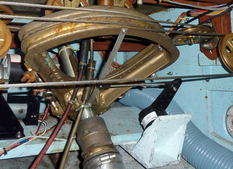
Don't Limit Yourself
As long as the RPS is mounted firmly, does not over swing it's capabilities, and is aligned correctly with the rudder there is no right or wrong way to install an RPS.
On this particular radial drive I fabricated an aluminum piece that is bolted between the radial drive stop and the radial drive and moves the RPS's pivot point closer to the rudder post in order to prevent "over-swinging" the rudder transducers capabilities. The RPS is them mounted upside down to the cockpit sole.
17-MAY-2012
Another Method
For this installation a piece of G10 "L" channel and an aluminum plate were used to mount & orient the RPS to the vessel. The RPS pivot head was mounted to the underside of the tiller arm for the linear drive.
04-JUN-2012
Many Ways to Skin the Cat
On this vessel it was easiest to drill, tap & mount a small piece of stainless bar stock to the quadrant and then create a bracket for the Simrad RPS.
16-SEP-2016
Get Creative
When installing an RPS, think outside the box, but try and utilize what you already have there to work with. On this boat the RPS was mounted to one of the stringers using a piece of "L" channel. The tiller arm was drilled and tapped for the RPS pivot inside of where the linear drive pivot point is.
06-SEP-2012
Fittment
When fitting an RPS it's not 100% necessary for the arm to always be level. There is some allowable offset allowed between the tiller arm pivot and the RPS pivot. In this case no shimming was necessary in order to avoid binding.
03-MAY-2016
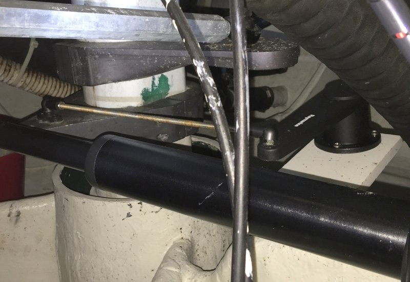
Another Upside Down RPS
On this vessel it simply made more sense to use what was there and mount the RPS to the bulkhead and then to the radial drive. Mounting it to the autopilots bronze tiller arm would have been considerably more complicated.
Good luck and don't be afraid to install that critical rudder position sensor...
MAY-2006
Help Support This Site
Like what you saw or read in this article? Was it helpful? Could the information save you some money? Would you like to see more articles like this?
If so feel free to donate, support the site, and keep it growing. Please DO NOT feel obligated at all. If you like it and want to make a donation, please do. Your donations help keep the content coming and also help keep it FREE.
Click the DONATE button below if you would like to make a donation via PayPal.