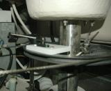
In this picture you can see the steering systems radial drive and the Starboard shim I fabricated to attach the rudder position sensor to.
A rudder position sensor is really just another navigation system transducer. The RPS tells the autopilot course computer where the rudder is at all times. This greatly helps the AP's course computer in holding an accurate course. Over the last ten or so years AP manufacturers have tried very hard to "program out" the RPS by adding rate gyros, prediction & behavior learning software etc. etc. yet with all this technology nothing improves AP performance like a rudder position sensor.
On low end price point autopilots, such as Raymarine's wheel pilot systems, the RPS, which used to be standard equipment, is now optional. In my experience the RPS is not "optional" if you desire the best performance. For coastal cruising you can sneak by without one but your AP performance will always be better with one.
For this particular installation I chose SS tube and Starboard marine lumber. Starboard is a high modulus engineered plastic sheet product available in thicknesses to 3/4 inch. Starboard is impervious to moisture and rot and is very well suited for certain uses on a boat. It works & cuts similarly to wood and is a tremendously useful but very expensive product. For small jobs like this I always save "Starboard" end cuts or waste material from bigger jobs..
On many Edson radial drives, some folks refer to them as "quadrants" but the round ones are technically called radial drives, there are two 5/16 threaded holes already drilled and tapped into its surface for the rudder stop.
I simply measured the hole center to hole center of these 5/16 threaded holes and transferred the measurements to the Starboard shim using a set of calipers. I then drilled the two holes and mounted the ball, which is RPS's ball & socket pivot point to the Starboard perfectly centered between the two 5/16 holes. With the ball mounted, and screwed into the Starboard shim, I then bolted the shim to the quadrant. In the picture you can see the two 5/16 bolt heads with the ball mount for the sensor in between them.