


|
|
|
|
|
|
| bartenderdave | profile | all galleries >> Surf Scoter: A Cuddy Cabin Bartender >> 20-4 Bartender Part III >> Electrical | tree view | thumbnails | slideshow |
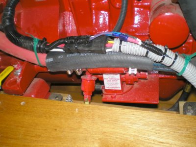
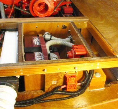 Battery box with added 40 A circuit, leading to helm. Fused within 7 inches of battery, as required. |
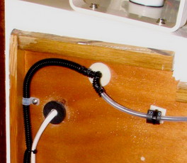
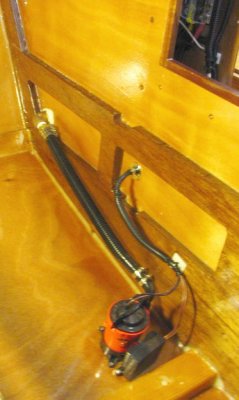 Cuddy bilge pump, forward of the bulkhead. Aft pump on the other side. Note chafe protection through bulkhead. |
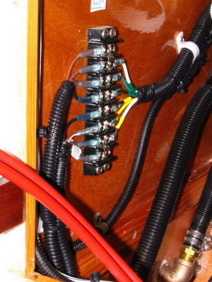 Pump wiring at terminal block inside helm above floorboards, for ease of replacement. Butt connectors drier but harder to servi |
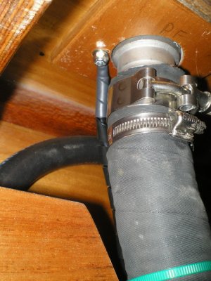
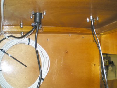
 VHF antenna entry cuddy port corner; drip loop and chafe protection (black fuel hose). |
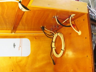 Cables forward of the helm. L to R: GPS/sounder; GPS antenna; VHF cables; allaround power. |
 VHF and allaround power, rear of cuddy bulkhead; chafe protection is household TV cable pass-throughs. |
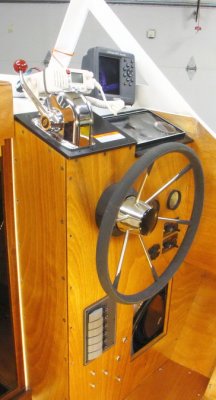 Where it (almost) all goes; VHF to the left; GPS/sounder to the right on the dashboard. |
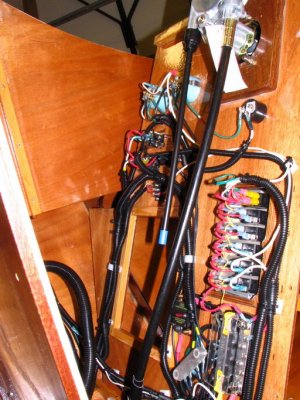
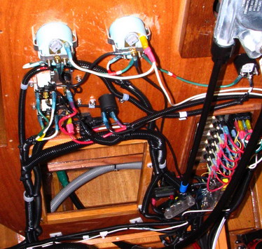
 Port view of helm innards; rear panel falls back, for easier wire-up and service. Succeeding photos: details inside helm |
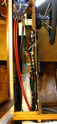
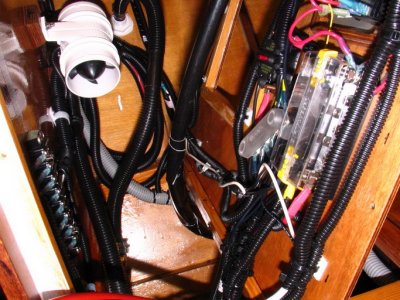 Major split loom-enclosed runs entering helm area from below or making low passes below. Blower hose removed for visibility. |
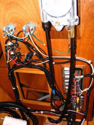 Rear of helm; gauges and bilge pump controls to left; major switch panel lower right behind steering cable. |
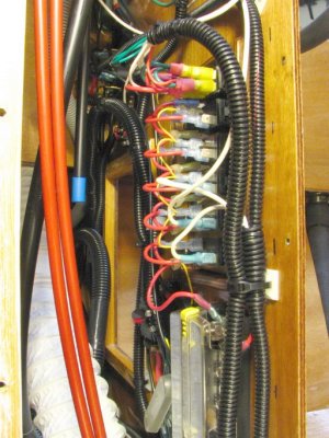
 Side view of switch panel and bus bars: one: supply plus return/common ground point;, the other: return/common ground point. |
 Closeup of switch panel rear; quick disconnects galore. |
 Detail of fuel gauges; accessory plugin below gauges; oil pressure / coolant temp buzzer under steering right side. |
 Westerbeke-provided harness to instr. panel; breaker protection on engine; chafe protection underneath. |
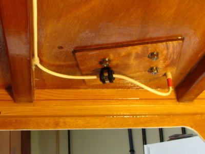
 Ground to port fuel filler; ties to port tank ground, running forward with fuel sender wires (next photo). |
 Port fuel filler ground joining tank ground; sender wiring joins loom en route to helm common ground point |
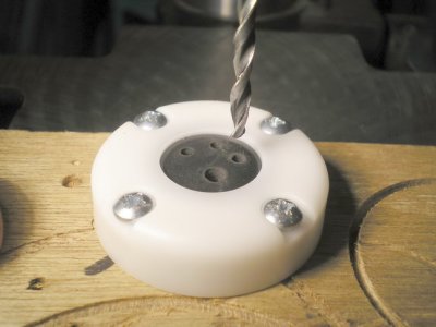 Blue Sea Cable Clams route cables through the cuddy cabin top. Drilled holes and slits in rubber stoppers permit easy installat |
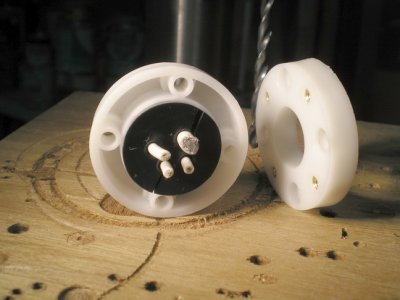 Trapping stopper between halves of the clams compresses it tightly onto the cables; a little 303 helps here. |
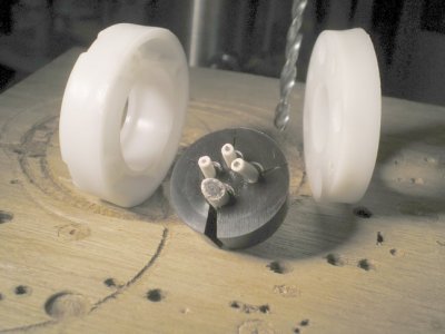 The same clam, released. That huge slit compresses tightly when installed, believe it or not! |
 Larger clam passes connectors up to about 1.4 inches in OD. |
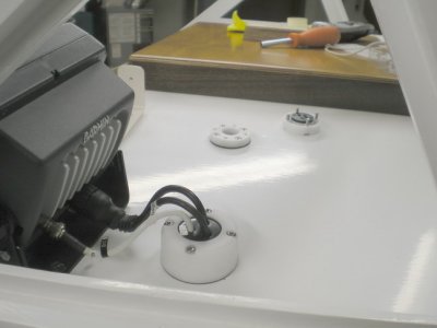
 Here is the underside of the installation in the previous photo. |
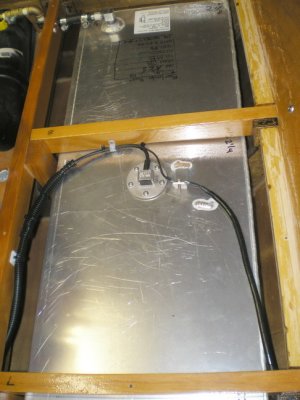
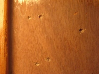 Bilge pumps initially mounted directly to hull; Dremeled holes to solid material. |
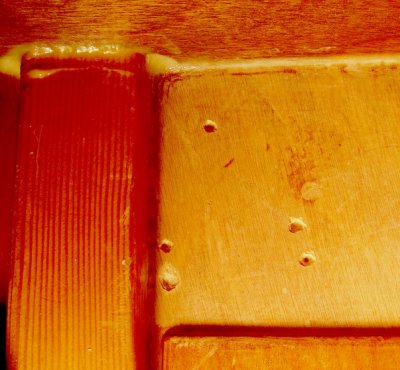 Aft holes, also Dremeled; another layer of 3/8ths will be laid on top and new holes made. |
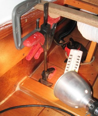 Clamp up, aft location; Thick filled epoxy between mounting ply and hull protects hull from rot. |
| comment | share |
| Tom | 31-Dec-2009 21:54 | |