photo sharing and upload picture albums photo forums search pictures popular photos photography help login
William Shaheen | profile | all galleries >> Astronomy - Astronomical objects, images and astronomy related projects >> Cave Creek Observatory Construction tree view | thumbnails | slideshow

Cave Creek Observatory Construction

Cave Creek Observatory Construction

The purpose of this gallery is to document the construction of Cave Creek observatory, demonstrating the construction details and materials used. The observatory is no longer in operation as we have moved to another location (Gold Canyon, AZ).

Cave Creek, Arizona is located north of Phoenix and construction began in March of 2000 and after a respite for the summer heat was completed in late fall of the same year.
The floorplan is 10x12 ft. and the wall height is 5 ft. 10 inches.
The observatory houses a Celestron C11 from a CM1100 on a CI700 mount.

Numbered photos were taken with an Olympus 2020Z and resized to 640x480. (The first 2 images are scanned photos.) The photo id indicates the date - 00050411 is photo nbr 11 taken 05/04/00.

Bill Shaheen Superstition Mountain Astronomical League (founded March 20, 2009)

WJShaheen@outlook.COM


*** Updated 18-Jan-2003
*** Updated 03-May-2007
*** Updated 25-Jan-2020 for new email address.

Site selection and alignment. View looking north. The white pole to the right of the Giant Saguaro cactus is to align on Polaris. (Not terribly important at this stage.)
December, 1999.

00010101.jpg
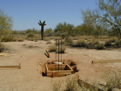
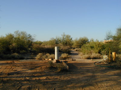
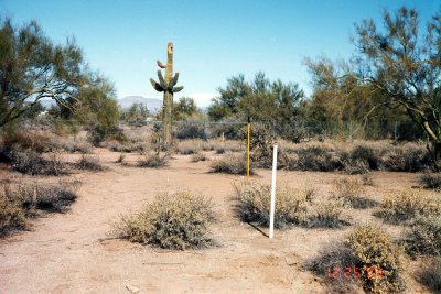
Obsconst01

Site selection and alignment. View looking north. The white pole to the right of the Giant Saguaro cactus is to align on Polaris. (Not terribly important at this stage.)
December, 1999.

00010101.jpg

Boy, it sure helps to have a neighbor (Joe) who has access to a backhoe.
Dec. 26, 1999.

00010102.jpg
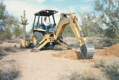
Obsconst02

Boy, it sure helps to have a neighbor (Joe) who has access to a backhoe.
Dec. 26, 1999.

00010102.jpg

The mounting plate on the pier is aligned within 1/2 degree of the pole star and the telescope base has a 7 degree azimuthal adjustment range.
00050411.JPG

The mounting plate on the pier is aligned within 1/2 degree of the pole star and the telescope base has a 7 degree azimuthal adjustment range.

The base is 32 in. by 32 in. by 42 in. deep. The column is 48 in. tall and 12 in. in diameter. The hole was backfilled prior to pouring.
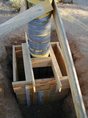
00050412.JPG

The base is 32 in. by 32 in. by 42 in. deep. The column is 48 in. tall and 12 in. in diameter. The hole was backfilled prior to pouring.

The top disk was to hold the rebar in place while pouring the bottom and was then removed to pour the column.
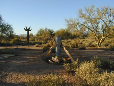
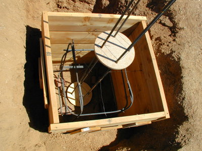
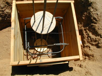
00052803.JPG

The top disk was to hold the rebar in place while pouring the bottom and was then removed to pour the column.

I have to admit, I reworked the footing several times (adjusting and tightening the re-bar, etc.).
View looking north.
00052804.JPG

I have to admit, I reworked the footing several times (adjusting and tightening the re-bar, etc.).
View looking north.

Permanent pier footing.
00052805.JPG

Permanent pier footing.

Prepped for pouring concrete. Note the machined plate is mounted with a wood frame around the cardboard tube. The tube was reinforced with duct tape and well that it was.
The tube was not actual Sonotube(tm) and it did bulge under the pressure.
00060301.JPG

Prepped for pouring concrete. Note the machined plate is mounted with a wood frame around the cardboard tube. The tube was reinforced with duct tape and well that it was.
The tube was not actual Sonotube(tm) and it did bulge under the pressure.

A closer view of the mounting plate - 2 plates welded together. The top plate is 5-1/2 in. to match the electronics cylinder of the CI700 mount.
*** See updated photo below - Jan. 2003.
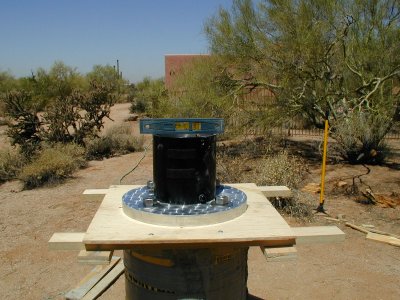
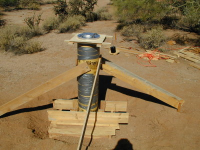
00060302.JPG

A closer view of the mounting plate - 2 plates welded together. The top plate is 5-1/2 in. to match the electronics cylinder of the CI700 mount.
*** See updated photo below - Jan. 2003.

How's this for level? Although, the telescope's latitude adjustment will correct leveling in the north-south axis. View looking directly west.
00060504.JPG

How's this for level? Although, the telescope's latitude adjustment will correct leveling in the north-south axis. View looking directly west.

View looking north. The 4 pieces of 1x2 strip straddle the form tube in order to center the the assembly on the pier. The J-bolts are 3/4 in. by 12 inches.
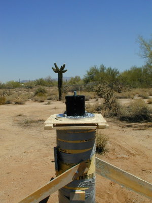
00060506.JPG

View looking north. The 4 pieces of 1x2 strip straddle the form tube in order to center the the assembly on the pier. The J-bolts are 3/4 in. by 12 inches.

Permanent pier poured June 5, 2000. View looking northwest.
00060510.jpg

Permanent pier poured June 5, 2000. View looking northwest.

Quikcrete (tm) tube and mounting plate removed. View looking south.
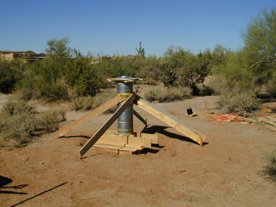
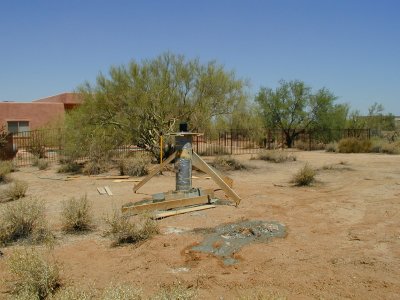
00060701.JPG

Quikcrete (tm) tube and mounting plate removed. View looking south.

The telescope at home on its pier.
Celestron C-11.
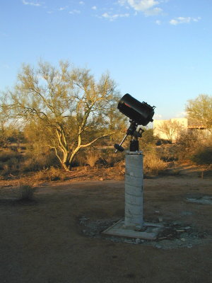
00060812.JPG

The telescope at home on its pier.
Celestron C-11.

Two of the eventual 5 beams were supported by pre-cast concrete piers sunk in the ground to prevent skidding.
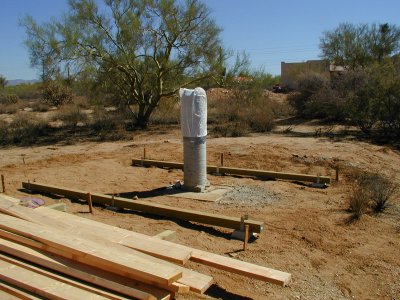
00090906.JPG

Two of the eventual 5 beams were supported by pre-cast concrete piers sunk in the ground to prevent skidding.

More pressure-treated 4x4 beams were added for support and the joists were then laid across them.
Since the floor joists rest directly on the length-wise beams the floor is very solid. The stringer joists simply attach to the joists. Concrete blocks were later added for support.
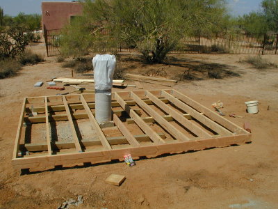
00091001.JPG

More pressure-treated 4x4 beams were added for support and the joists were then laid across them.
Since the floor joists rest directly on the length-wise beams the floor is very solid. The stringer joists simply attach to the joists. Concrete blocks were later added for support.

Framing completed and rear roll-off support then added. For the roof, I first made two carriages with six 5-1/2in wheels and then added the trusses. The wheels are mounted on roller bearings and are rated at 450 lbs each.
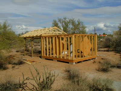
00102118.JPG

Framing completed and rear roll-off support then added. For the roof, I first made two carriages with six 5-1/2in wheels and then added the trusses. The wheels are mounted on roller bearings and are rated at 450 lbs each.

After installing the roofing (shingle and all), it became difficult to move but that turned out to be binding which was fixed by shifting the top-plates inward. Still, use 4 wheels per side, not 3.
00102130.JPG

After installing the roofing (shingle and all), it became difficult to move but that turned out to be binding which was fixed by shifting the top-plates inward. Still, use 4 wheels per side, not 3.

Roof detail. Note the carriage that rolls on the top plate.
The wheel is just visible at the center of the picture.
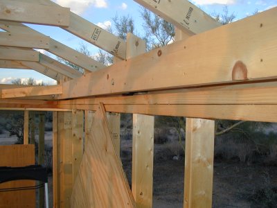
00102602.JPG

Roof detail. Note the carriage that rolls on the top plate.
The wheel is just visible at the center of the picture.

The wheels were from the Luna Caster and Truck Corp., model nbr 6034; they are sandwiched between a 1x6 and a 1x8 12 footers and another 1x6 was later added to the inboard side.
Just go with a 2x6.
00102604.JPG

The wheels were from the Luna Caster and Truck Corp., model nbr 6034; they are sandwiched between a 1x6 and a 1x8 12 footers and another 1x6 was later added to the inboard side.
Just go with a 2x6.

The upright pieces of 2x4 were beveled to match the angle of the rool (22-1/2 deg.). This provided an easy attachment point for the roof trusses. Note the small pieces of 1x6 that when added to the thickness of the wheel fit within the carriage sides (the width of the 2x4 uprights).
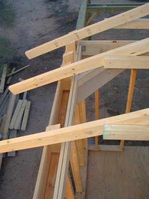
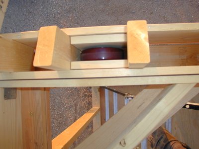
00102605.JPG

The upright pieces of 2x4 were beveled to match the angle of the rool (22-1/2 deg.). This provided an easy attachment point for the roof trusses. Note the small pieces of 1x6 that when added to the thickness of the wheel fit within the carriage sides (the width of the 2x4 uprights).

Truss detail. basically an 'A' frame with a piece of 1x6 at the top and a 2x4 cross-member. These attached easily to the carriage uprights and are 2 ft. on center.
The struts were then added between the trusses.
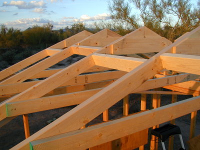
00102607.JPG

Truss detail. basically an 'A' frame with a piece of 1x6 at the top and a 2x4 cross-member. These attached easily to the carriage uprights and are 2 ft. on center.
The struts were then added between the trusses.

Here's a larger view to show how it comes together.
The two 2x4's that form the top of the A were cut at the 22-1/2 deg. setting on a power miter saw (best investment I ever made).
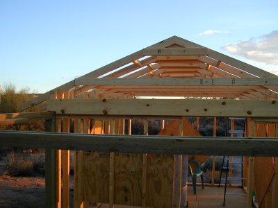
00102609.JPG

Here's a larger view to show how it comes together.
The two 2x4's that form the top of the A were cut at the 22-1/2 deg. setting on a power miter saw (best investment I ever made).

And, here it is after the roofing and siding were installed.
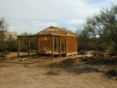
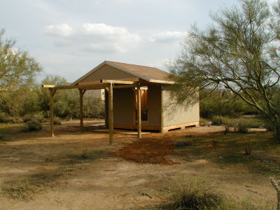
00110502.JPG

And, here it is after the roofing and siding were installed.

And, of course, the view from the south.
The siding by the way is a 1/2 inch stucco finish, instead of the lesser expensive t1-11 stuff.
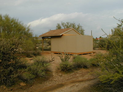
00110504.JPG

And, of course, the view from the south.
The siding by the way is a 1/2 inch stucco finish, instead of the lesser expensive t1-11 stuff.

Viewed from the north, the pier is visible thru the doorway.
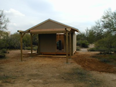
00110505.JPG

Viewed from the north, the pier is visible thru the doorway.

Exterior finished - November 5th, 2000.
00110512.JPG

Exterior finished - November 5th, 2000.

And finally the telescope is where it belongs.
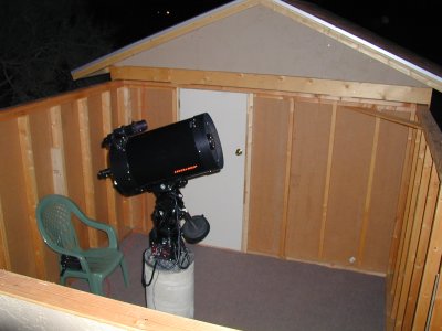
00110706.JPG

And finally the telescope is where it belongs.

...and so am I - observing at last!
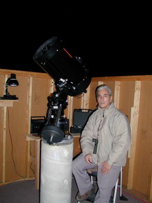
00111302.JPG

...and so am I - observing at last!

Imaged thru the 11 in. f/10 SCT using the Oly C2020Z at 10:55pm MST 11/17/2000 with a 7.4mm eyepiece at F3.2 for 1/10th second, ISO 100.
00111716.JPG

Imaged thru the 11 in. f/10 SCT using the Oly C2020Z at 10:55pm MST 11/17/2000 with a 7.4mm eyepiece at F3.2 for 1/10th second, ISO 100.

Jupiter thru the C11 with a 9.7mm eyepiece.
F3.2 @ 1/10th second, ISO 100.
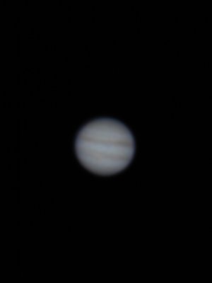
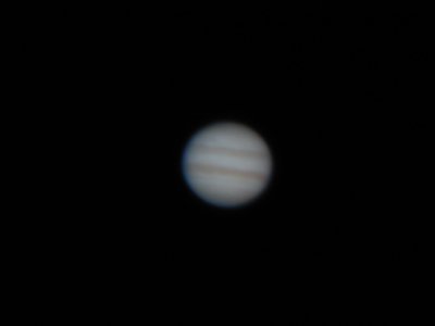
00111901.JPG

Jupiter thru the C11 with a 9.7mm eyepiece.
F3.2 @ 1/10th second, ISO 100.

Saturn thru the C11 with a 9.7mm eyepiece.
F2.8 @ 1/2 second at ISO 100.
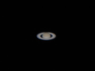
00111908.JPG

Saturn thru the C11 with a 9.7mm eyepiece.
F2.8 @ 1/2 second at ISO 100.

Update - Jan. 2003. Some improvements made over the last couple years. Additional ventilation and a 'sunwall' on the west side have been installed. The sunwall is very effective - providing shade from the afternoon sun.
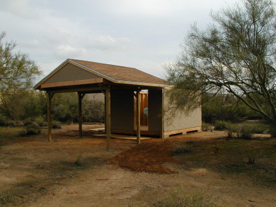
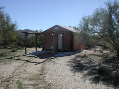
03011810.JPG

Update - Jan. 2003. Some improvements made over the last couple years. Additional ventilation and a 'sunwall' on the west side have been installed. The sunwall is very effective - providing shade from the afternoon sun.

A few views from the roof to give you a better idea of the floorplan.
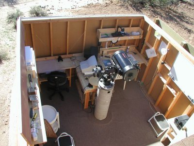
03011803.JPG

A few views from the roof to give you a better idea of the floorplan.

Looking directly south.
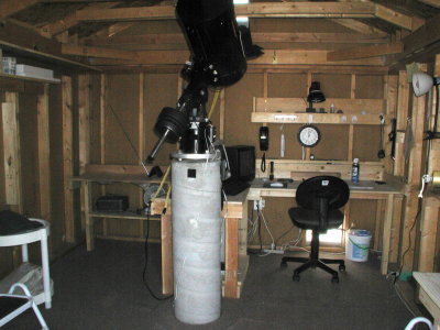
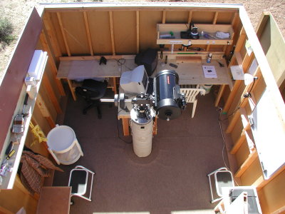
03011808.JPG

Looking directly south.

There is a table across the entire south wall with an extension in the middle out to the pier.
I do most observing and imaging to the east (left) but can simply rotate the monitor to the other side of the table.
03011827.JPG

There is a table across the entire south wall with an extension in the middle out to the pier.
I do most observing and imaging to the east (left) but can simply rotate the monitor to the other side of the table.

The pier is 57 inches from the south wall and 5' from the east and west walls, simpy due to the south wall (10 ft.) installed inside the two side walls. It is 7' from the north wall.
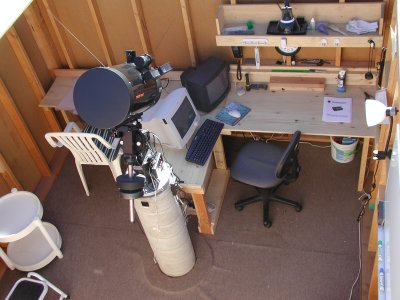
03011824.JPG

The pier is 57 inches from the south wall and 5' from the east and west walls, simpy due to the south wall (10 ft.) installed inside the two side walls. It is 7' from the north wall.

Looking nortwest. Installed another table in the corner. The 10' x 12' footprint affords plenty of room for ancillary items. But, a 10 x 10 would be more than adequate.
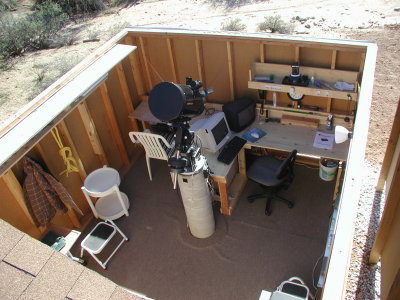
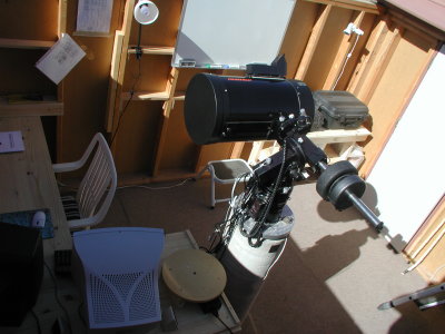
03011809.JPG

Looking nortwest. Installed another table in the corner. The 10' x 12' footprint affords plenty of room for ancillary items. But, a 10 x 10 would be more than adequate.

Having made my way safely back to earth, a view from the doorway.
03011817.JPG

Having made my way safely back to earth, a view from the doorway.

A closer view of the workstation area, shot earlier.
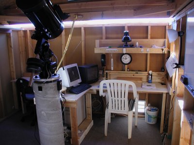
03011801.JPG

A closer view of the workstation area, shot earlier.

Here is a detail of the attaching plate. It is a composite of a 12 in. plate with the middle cut-out and welded to a 5-1/2 in. plate to match the electronics cylinder of the CI700 (the black device). The height to the top of the plate (bottom of the cylinder) is exactly 42 inches. This closely matches the original height of the field tripod - 43 inches - and works well for me, being 5' 7-1/2 inches. (Notice I got that extra 1/2 inch in there :O)
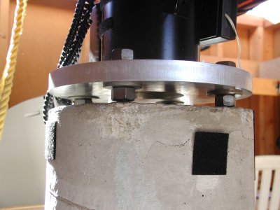
03011814.JPG

Here is a detail of the attaching plate. It is a composite of a 12 in. plate with the middle cut-out and welded to a 5-1/2 in. plate to match the electronics cylinder of the CI700 (the black device). The height to the top of the plate (bottom of the cylinder) is exactly 42 inches. This closely matches the original height of the field tripod - 43 inches - and works well for me, being 5' 7-1/2 inches. (Notice I got that extra 1/2 inch in there :O)