20-DEC-2012
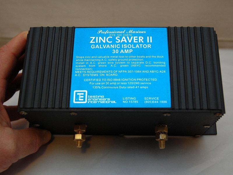
A 30A Galvanic Isolator
Ok so just what is a Galvanic Isolator (GI), why do I need one or have one & why on Earth would I need to test one?
Why do I need one? A GI is a device that is inserted, in series, into the green grounding wire (safety ground) of your shore power feed to help minimize or reduce the effects of galvanic current from flowing into your vessel. While blocking galvanic level current it also has to allow for the passage of AC fault current. GI's are a simple hook up and installation. If plugging in at a marina a GI is the bare minimum level of protection a boater should have. I do prefer an isolation transformer (IT) to a GI but the conversation of a galvanic isolator vs. isolation transformer is a whole other discussion & topic.
To install a GI all one needs to do is to break the green wire after the shore power inlet but before the AC panel. Cut the green wire in two, crimp on two terminals and connect them to each stud. Very simple. The purpose of a GI is to block low voltage galvanic level DC current while still allowing any fault current to pass through the green wire to ground and allow it to activate fault protection devices.
This blockage of low voltage stray DC current is achieved by using two diodes in each direction. Each diode drops approximately .6V or requires more than .6V to open and "Flow". Two of them in series results in approximately a 1.0V - 1.2V threshold for blocking stray DC current. They normally have two diodes in each direction so the green wire is not "check valved" and acts just like a wire would. The only difference is it acts as one that won't pass voltages below 1.0V - 1.2V. Simple and pretty effective at blocking galvanic level current.
What is a diode? Think of a diode as an electrical check valve. It allows current to flow in only one direction but not in the other direction. One of the inherent traits of diodes is the voltage drop associated with them, which is usually around 0.6V. In a galvanic isolator application however, they have used this often assumed bad trait of a diode to an advantage. By wiring two diodes in series you now have a device that can block any stray current below 1.0V - 1.2V from flowing into or out of your vessel.. This essentially blocks any DC currents caused by dissimilar metals being connected in the marina when you "plug in".
20-DEC-2012
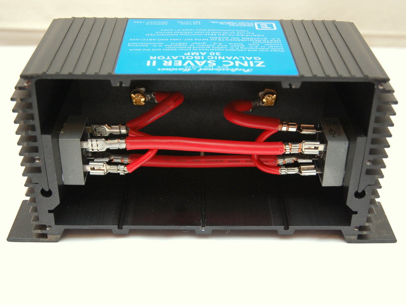
Simple Devices
As I said above these are simple devices. When opened up you can see just how simple. Keep in mind that this particular model no longer meets the current ABYC safety standards and I will get to that in a moment. On the back wall we can see the two wires going to the gold plated studs. This is where your green grounding wire would be cut and connected to. Inside we can see the two diodes which allow current to flow in both directions but at the same time blocking voltages below 1.0 - 1.2V.
So why do I need to test my GI? Remember in the last paragraph when I mentioned that this particular GI no longer meets the current ABYC safety standards? Well,there is a very good reason for that.
Think back to when I described where a GI gets installed? It goes in the GREEN SAFETY GROUND WIRE! So now what happens if one or both of those diodes get blown? NO SAFETY GROUND....! There were far to many incidences of boats with GI's that completely lost their safety ground connection to shore due to failed diodes. A single lightning strike on a boat a few docks away could take out half the GI's in the whole marina and folks rarely even noticed.. Couple this with the fact that many more boats are not wired, on-board, to current safety standards where the AC green/grounding wire is bonded to the ships DC grounding bus and this means metallic parts of AC devices could become "hot" in the event of a fault. Hot cases and metallic parts of your boat spell the potential for electrocution or death to swimmers by electric shock drowning. The problem is that without the safety ground the fault protection devices will not trip as they should. This = BAD !
Below is a direct quote from Captain David Rifkin. He is perhaps the leading expert in marine electrical shock drowning deaths, bonding and corrosion.
"In the many boats I have tested with galvanic isolators, approximately 5% tested open circuited (meaning the boat did not have a connection to the marina grounding system) and the operators were completely unaware."
So 5% of the boats with GI's and an open circuited ground, does not sound like much but consider that with the millions of boats in the water there are potentially hundreds of thousands of GI's installed on boats. How many boats in your marina? 100? So if 5 of those boats are completely lacking a green safety ground wire do you want to go swimming in your marina??
So just what does meet the current standards for GI's? The ABYC standards for galvanic isolators have changed a few times. First it required "active monitoring" and remote idiot lights so an owner would know they had a working GI and still had their safety ground intact. This "active monitoring" added significantly to the cost of GI's and was a total PITA in terms of parasitic loads because it had to be "wired in" to more than just the green wire.
A number of years ago a company called Dairyland Electrical Industries, or DEI for short, invented/brought the "fail safe" galvanic isolator to the marine market. This advancement brought the simplicity back to the GI, did away with the idiot lights and related circuitry, but added a major new safety feature, "fail safe".
Fail safe means that these devices fail closed instead of open as a normal diode would. By failing closed you only lose galvanic protection but not your SAFETY GROUND wire....! According to Henry T., one of the owners of DEI, they have not had a single failure of a DEI Fail Safe galvanic isolator where it failed "open", even to lightning strikes. A pretty impressive feat considering the number of failures that occurred with the older technology, like the one you see here.
Today companies such as Guest, ProMariner & DEI all make ABYC compliant galvanic isolators with the fail safe technology. Yandina also makes a GI but it does not meet the current ABYC safety standards. I do mention them though because they are at least 100% honest that the product does not technically meet the standards. Kudos to Yandina for being honest in a world of BS marketing hype.. If you are a mooring sailor who rarely stays at a dock the Yandina GI can be a good value. If adding a GI, for regular dock side use, I would advise going with a "fail safe" product so you don't lose your safety ground wire.
20-DEC-2012
How To Test
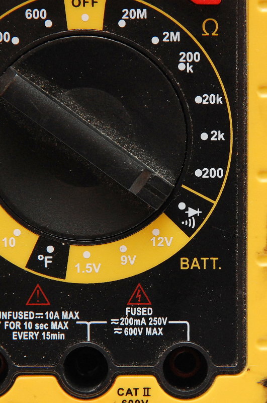
If you have an older non-fail safe isolator how do you test it? Perhaps the easiest method is to use a DVM like the one pictured set to the diode test function. On this particular meter the diode test shares a dial position with the Ω feature. Here it is set to test Ω.
20-DEC-2012
Switching To Diode Test
With this meter pressing the yellow button moves it from the Ω test to the diode test feature. The diode symbol can be seen on the left hand side of the meters screen.
20-DEC-2012
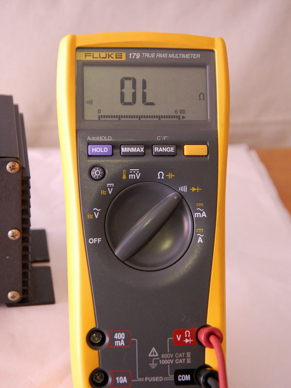
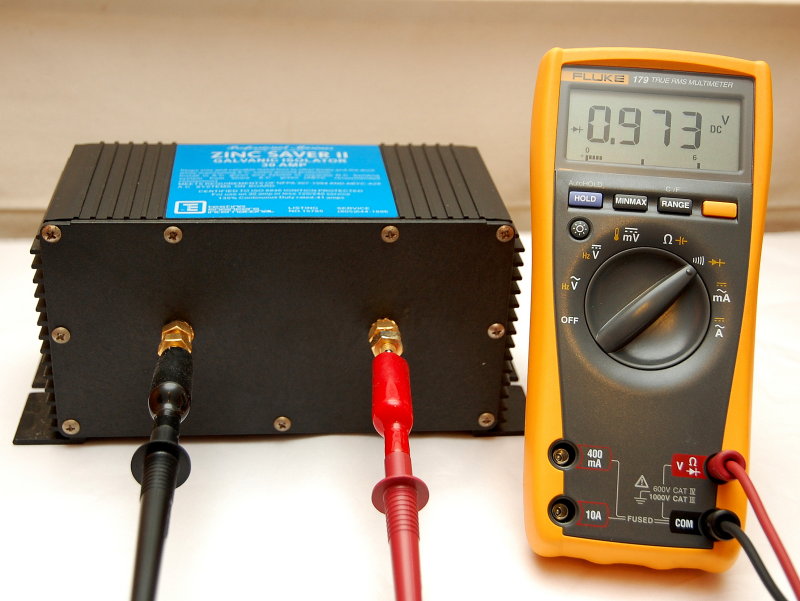
Connect Your Test Leads
First UNPLUG YOUR VESSEL FROM AC POWER !! With the AC power to the vessel OFF disconnect both green wires from the GI and connect your DVM leads to the studs.
If the diodes are working you should see a reading of .8 to 1.0. here the reading is .973..
If the diodes are bad you will not get a reading or will get the OL message (open leads) if using a Fluke. Older style galvanic isolators like this fail "open"...
20-DEC-2012
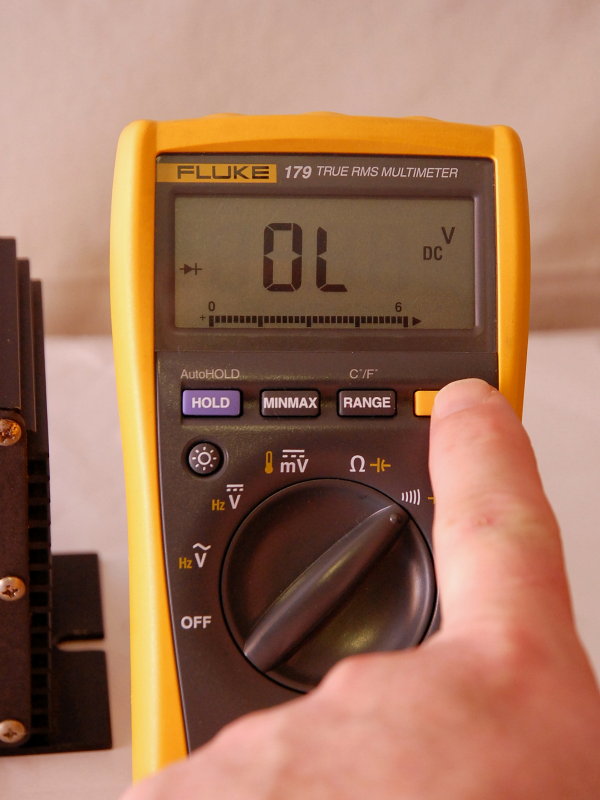
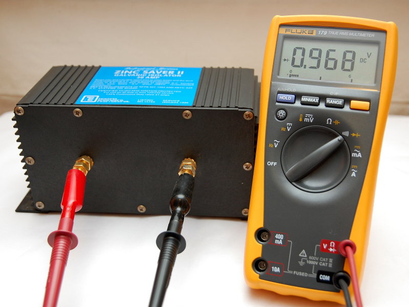
Now Reverse The Leads
Remember the current needs to flow in both directions and it is possible for one side to be blown and the other side still be fine.
Here the reading is .968 and well within range. You are allowed roughly a 10% variance from one side to the other so .968 and .973 are well within that spec at a 0.5% variance.
Despite being a relic, this isolator is still operable. If however you have an old isolator like this, and you keep your boat at a marina, I would strongly advise upgrading it to newer ABYC compliant unit. The other alternative is to regularly test your GI to ensure its operation.
My personal preference for GI's are the DEI isolators. I feel they are the most robustly built GI's on the market and you don't pay any more for them than you would another "fail safe" brand.. Again DEI has had ZERO GI failures that were not failed "safe" and this includes lighting strikes...
20-DEC-2012
You Don't Need A Fancy Meter
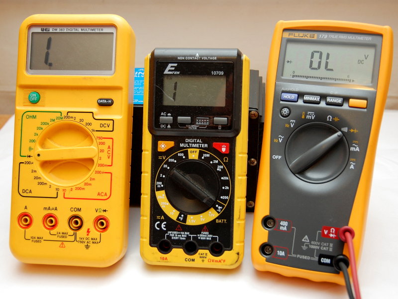
I love my Fluke equipment, and you'd need to pry it from my dead fingers, but for work like this even an inexpensive meter will do, provided it has a diode test function, and many "cheapies" do.
In this photo each meter has been set to the diode test function.
20-DEC-2012
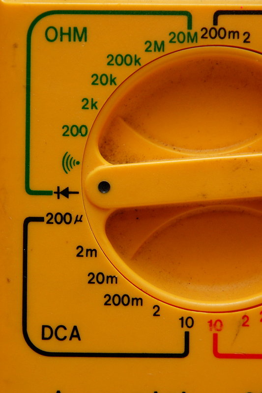
The Diode Symbol
The dial of this meter is pointing to the diode symbol. If a meter has the diode symbol it offers the diode test function.
20-DEC-2012
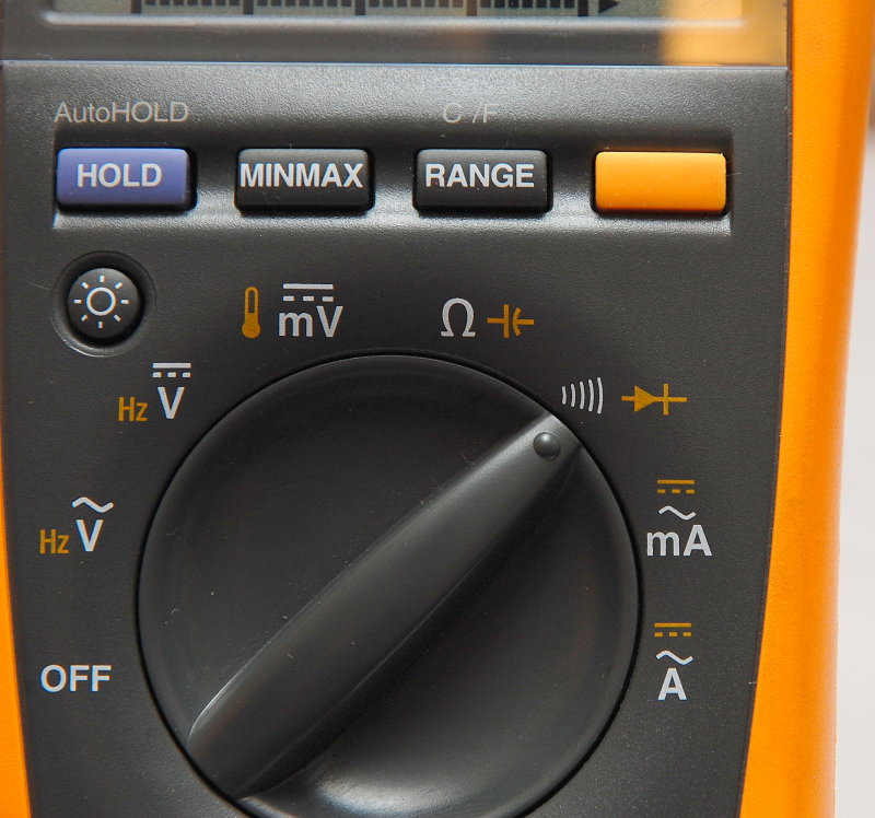
Set To Diode Test
On this meter the diode test function shares a dial position with the "audible" continuity test. This meter was about $20.00 at Wal*Mart. I bought it one day when I forgot my meter bag.....
20-DEC-2012
Diode Test
On the Fluke 179 you simply toggle between the diode test and Ω with the yellow button.
21-DEC-2012
Alternative Test
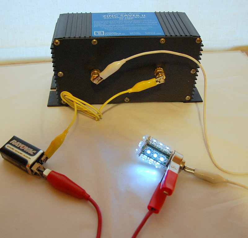
While I prefer to use the diode test functionality of a DVM you can do a quick and dirty test with a 9V battery and a 12V light bulb. I grabbed an LED bulb but I won't guarantee all LED bulbs will fire at sub 9V. You will get a dimly lit 12V bulb with a 9V battery but the test works. I only used the LED because it showed up better with the picture.
If you first connect your bulb direct to the 9V battery then test it through the isolator you will notice a change in brightness. This is caused by the voltage drop across the diodes and is 100% normal and should be expected.
Wire the 9V battery and light bulb as shown and the bulb should light if the diodes are good..
21-DEC-2012
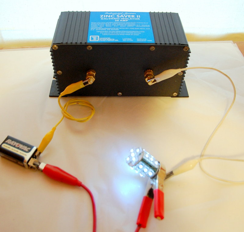
Reverse The Leads
Again, just like with the diode test function on the DVM you'll need to reverse the leads to check the flow in the opposite direction. The bulb should light.
Galvanic isolators are in the path of the safety ground for your vessel so it is critical that you know your GI is working. Newer GI's have either idiot lights that tell you it is on or are fail safe so there is much less need to worry about losing the safety ground.
This test is for older style GI's like the one pictured. There are still perhaps hundreds of thousands of boats with this style GI installed on them.
*******PLEASE CLICK BELOW FOR PAGE 2*******