


|
|
|
|
|
|
| fred harmon | profile | all galleries >> Galleries >> rearshock | tree view | thumbnails | slideshow |
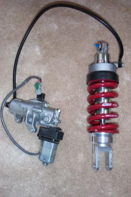 Works Performance GL1800 Shock with OEM Honda pre-load adjuster |
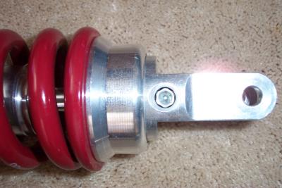
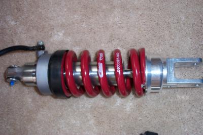 Works GL1800 Shock |
 The rebound dampening is adjustable via an allen screw on the bottom of the shock |
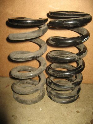
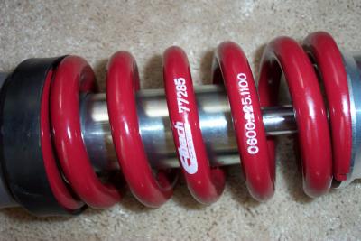 The spring has a 1,100 lb spring rate. The OEM shock has a 900 lb spring rate. |
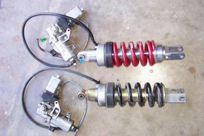 Here is a look at the OEM shock side by side with the Works Performance shock |
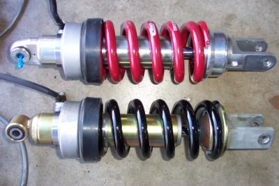 You can tell see a difference in the springs and shock body. |
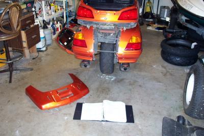
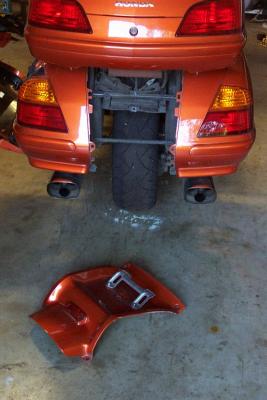 First, remove the rear wheel cover |
 Next, remove the seat |
 Then remove the cover for the latch assy inside the trunk |
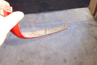
 Trim comes right off, once the two screws in the trunk are removed |
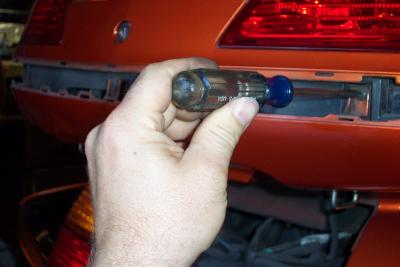
 Remove the four screws in the trunk (two each side) that hold on the trim pieces |
 Side trunk trim piece removed. Not two plastic threaded tangs that the screws go into |
 The rear trim piece is screwed on from the outside, and the srews are exposed once the side pieces are removed |
 Rear trim comes off after the two screws are removed |
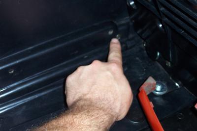 Screw locations inside trunk for trunk bottom cover |
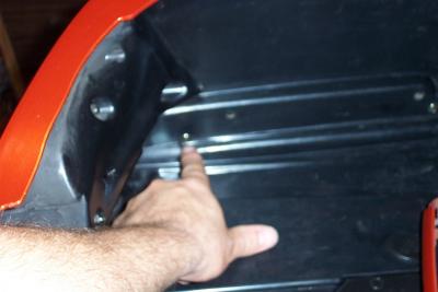 Screw location inside trunk for trunk bottom cover. |
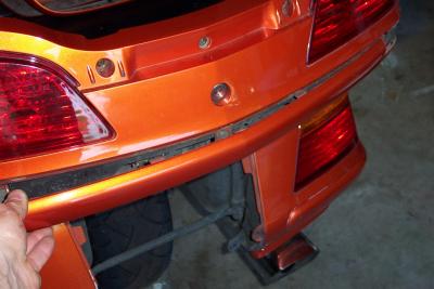
 Trunk bottom cover has two screws back by the tail lights that hold it on. |
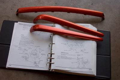 Trunk trim pieces removed |
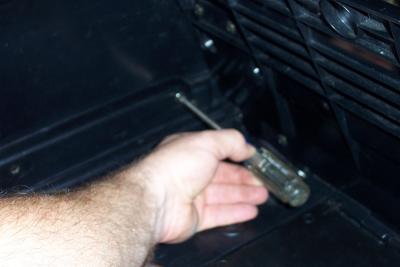
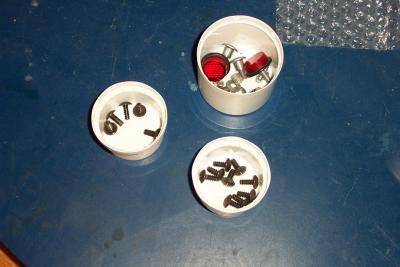 Keep hardware inside cups and seperated so you know what screws go back where. Most of the trim screws are all the same. |
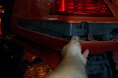 Trunk bottom cover pulls down and aft once all the screws are removed |
 Trunk bottom cover removed |
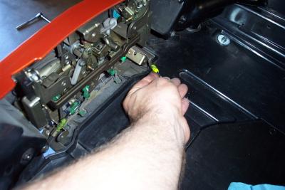 Next, dissconnect the cables for the saddlebag latches |
 Note saddlebag cable pulled free |
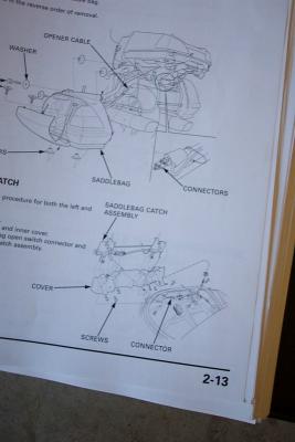 Now you have to find this connector and dissconnect it |
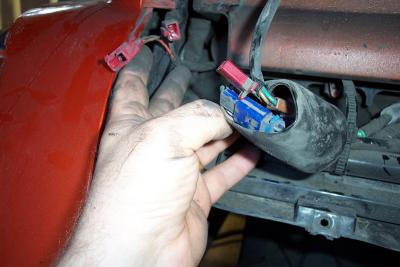 The red plugs are for the left bag and the blue plugs are for the right saddlebag |
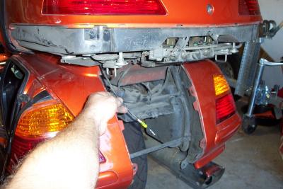
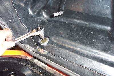 Now you can start unbolting the four bolts that hold on the saddlebag |
 Saddlebag inner bolt removal |
 Outter saddlebag bolt removal |
 Once the bolts are out, pull the bag out at the bottom and down making sure to clear the pocket at the top |
 saddlebag is now free |
 Saddle bag removed |
 Now you can see the frame rails for the bags |
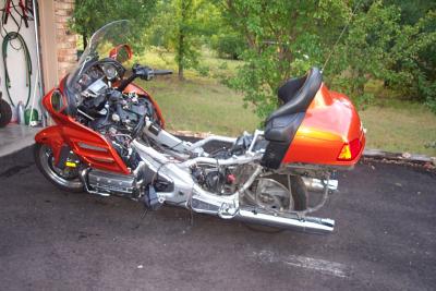
 Dirty bike. Dust collects all over the back end. |
 The next step is removing the top shelter and gas tank (covered in another photo series) |
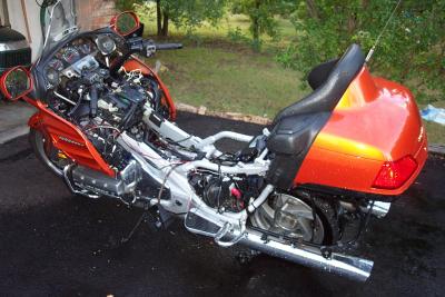 I hosed off all the dust and tried to clean it up as best I could before going any further |
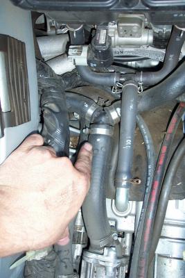 When you get the tank out, be sure to tighten these hose clamps. There are three more under these too. |
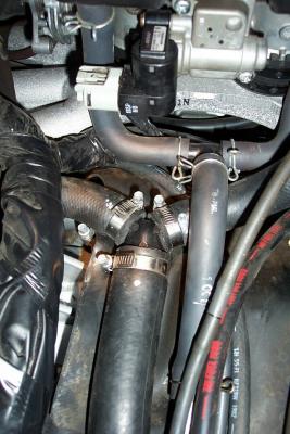 I turned the hose clamps. Cover them with hard rubber material to prevent them from rubbing a hole in the bottom of the gas tank |
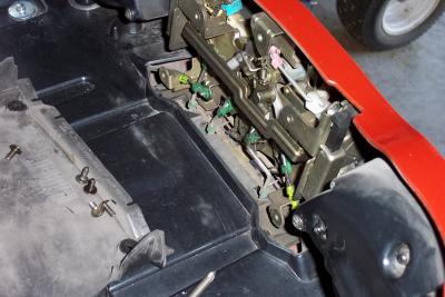
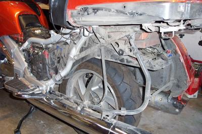
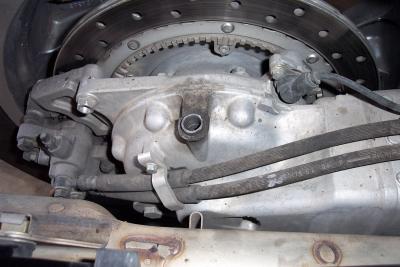
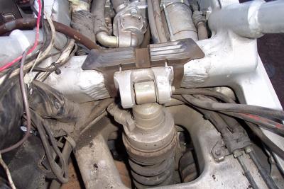 Here is the first look at the top shock mount |
 I also took this opportunity to inspect all my welds |
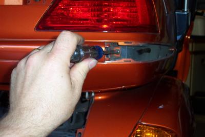
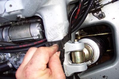
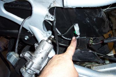
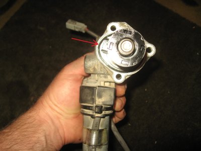
 Unplug the connector on the side of the unit |
 Weld checking |
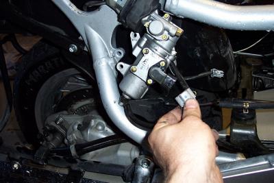
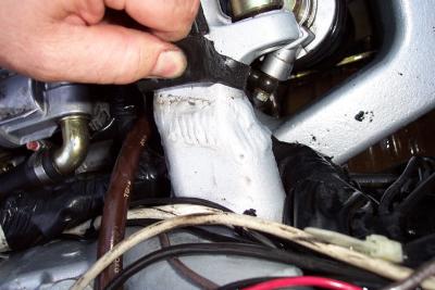
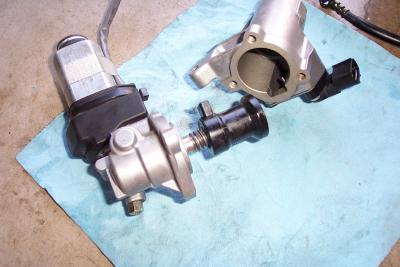
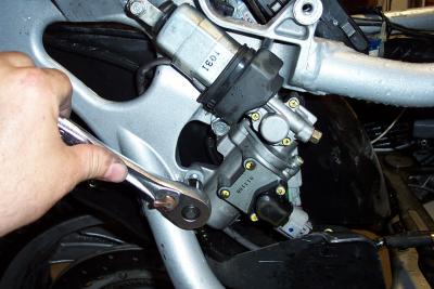 Next I removed the three bolts holding on the electrical/hydralic pre-load unit |
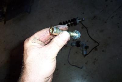
 This connector also has to be disconnected |
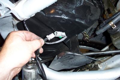 Unpluged connector |
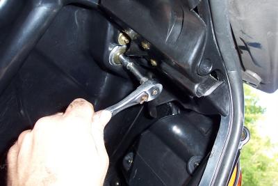
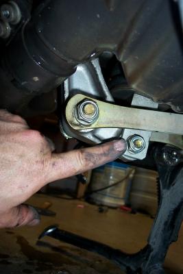 Here is the bottom shock bolt |
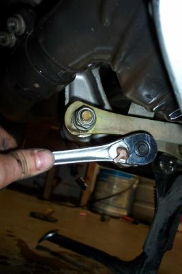 Removing bottom shock bolt |
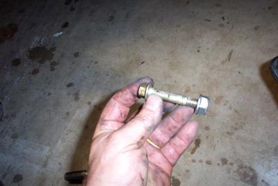 Bottom shock bolt pulled out |
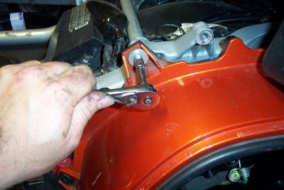
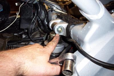 Top shock bolt |
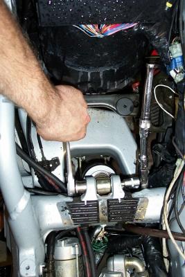 You have to hold both sides of the top shock bolt to remove it. One side uses an allen, the other a socket |
 Top shock bolt removed |
 Once both bolts are out, the shock comes right off |
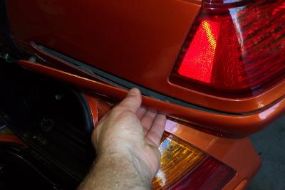
 When I removed the right saddlebag, I discovered the vent cap for the rear end was missing! |
 Here is a look at the top of the piston inside the rear shock hydralic drive unit, with the motor removed |
 Here you can see the worm drive and the plunger on the right angle drive unit and the housing for the hydralic unit. |
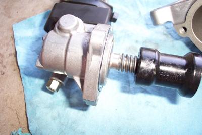 Here is a closer look at the plunger and worm drive on the motor |
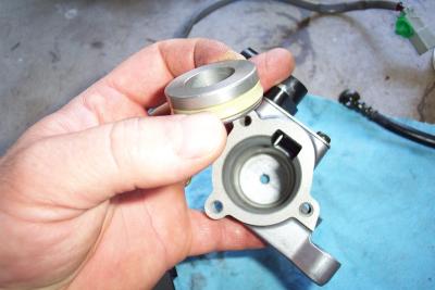 Here is the simple piston, removed from the chamber |
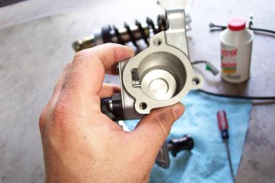 Here is another look with the piston re-installed |
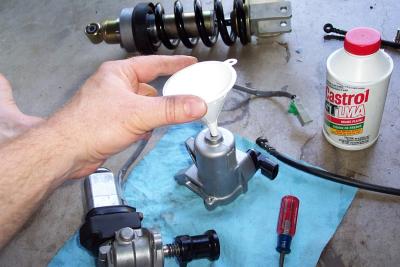 Refilling the unit through the bango bolt hole. I recommend 5 weight Honda suspension fluid (not the brake fluid pictured) |
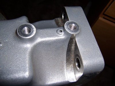 New Hole added under damper |
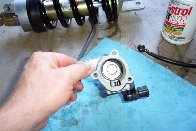
 Damper unit |
 ProgressiveRearSpring.jpg |
 RearShockActuator.jpg |
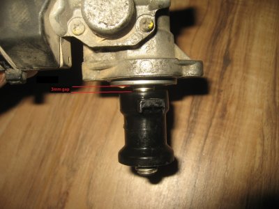 ActuatorGap.jpg |