


|
|
|
|
|
|
| fred harmon | profile | all galleries >> Galleries >> noisefilter | tree view | thumbnails | slideshow |
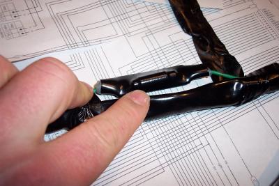 Honda P/N 32190-MCA-305 If you look close you can see the windings of a coil under the heat shrink |
 Here is the filter (iron core coil) added in the ground circuit on the 2003 models |
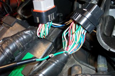
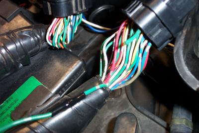
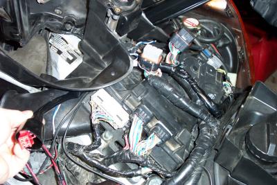
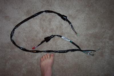 Here is a look at the whole harness and five of my piggies. |
 Note the use of sheilded cables in the new sub harness |
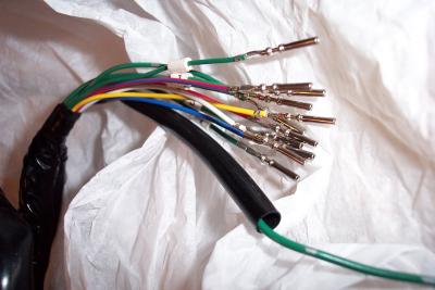 These are the wire ends with the crimped on pins that get inserted in the 34 pin radio connector |
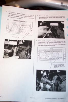 Instructions are provided with the kit |
 The first thing you do is cut and splice one ground wire to connect the coil (choke) |
 Completed splice |
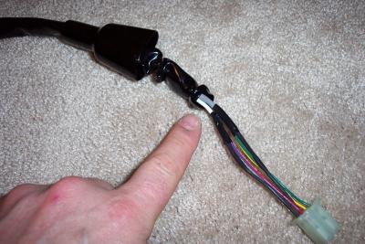
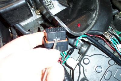 Next you push in a tab to release the pins |
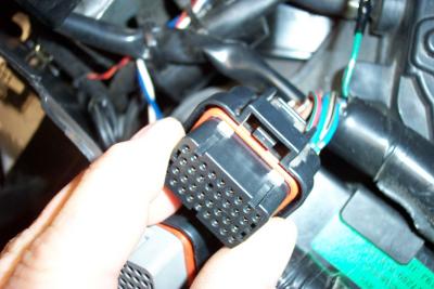 White tabs protrude from the other side when pins are released |
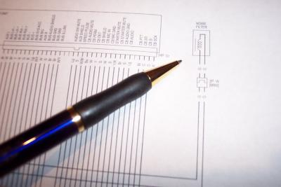
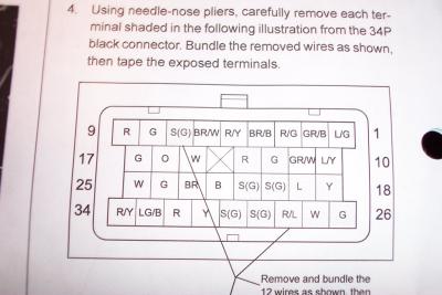 Diagram shows what pins get pulled. Pay carefull attention to pull the right ones. |
 This shows the pins in red that get pulled. Note that PIN # 7 does not get replaced, it stays empty. |
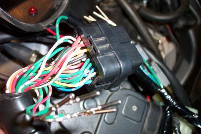 Pins simply pull out the back |
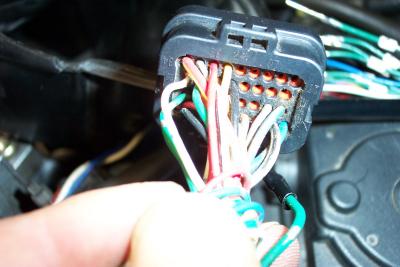 Here is the connector with pins removed |
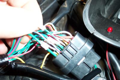 Replacement pins simply push into place |
 Push all pins in and then push white locking tab back into place |
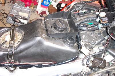 Route the new passenger harness down the right side of the gas tank |
 Route the riders harness up and to the left glove box pocket |