


|
|
|
|
|
|
| fred harmon | profile | all galleries >> Galleries >> Mic-Mutes microphone mute product | tree view | thumbnails | slideshow |
 Mic-Mutes kit |
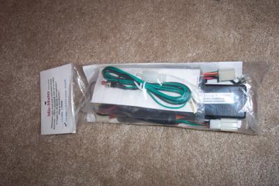
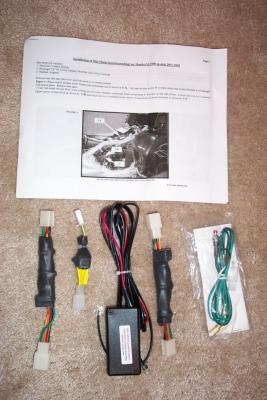 Contents and instructions |
 Mic Mute Kit |
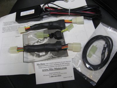
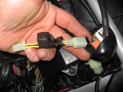
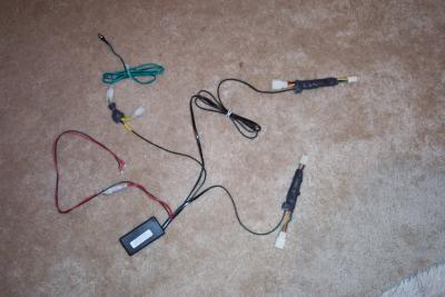 Here is a look at how the parts will be interconnected on the bike and electronic control module |
 If all else fails, read the instructions. They are very detailed |
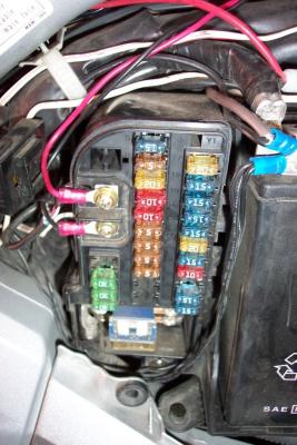 Accessory fuse box connections are straight forward |
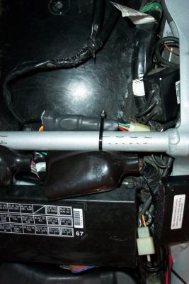
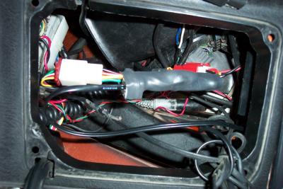
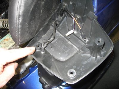
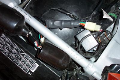 Mic-Mutes passenger headset adapter plugged into headset connector under seat and routed under crossbar |
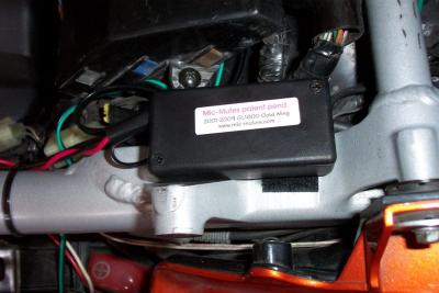 Location of Mic-Mutes Electronic Contol Module (ECM) |
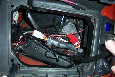
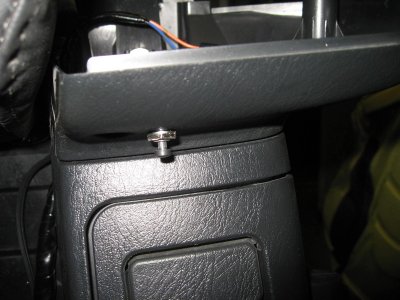
 Plugging in the lead for the PTT switch connector |
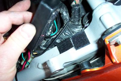 I used a bit of velcro to hold the ECM onto the frame |
 Once the all the connections are made to the headset adapter, I zipped tied it in place |
 I routed the wire behind the frame rail, using a coat hanger |
 Routing the wire up to the riders headset |
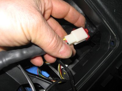 Connecting the lead for the riders headset |
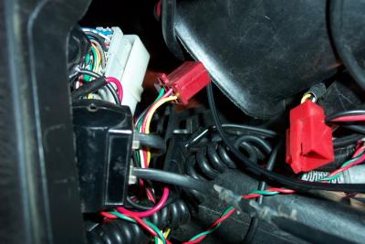 Red connectors under left glove box are where the riders headset adapter goes. Don't mind my FRS and Radar wire mess |
 One end of riders headset harness connected to headset adapter |
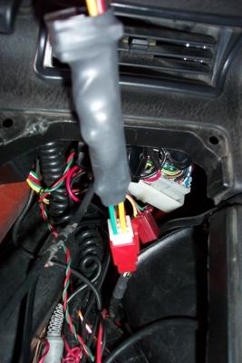
 Both ends of riders headset connected. Now all I have to do is get all these FRS and Radar and other wires back in place. |
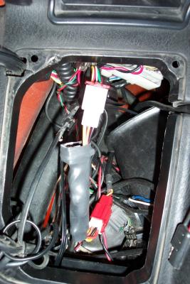
 Wires getting arranged. Hopefully I can get my glove blox back in when I am done |
 Mic-Mutes headset adapter fits nicely down in bottom of cavity |
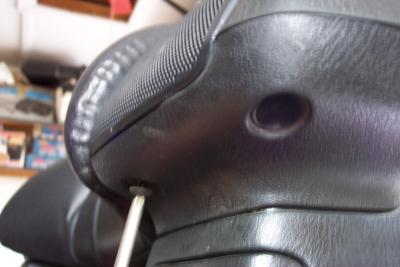 Removing three left rear speaker screws |
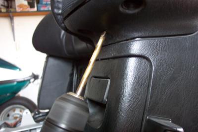 Then I drilled a 9/23 hole in the bottom for the switch. Be careful not to drill into your speakers!! |
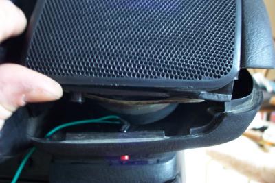 A look at the switch and wiring from the inside. Note tight clearance to speaker. I probably should have moved it off center. |
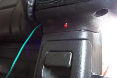 Switch and wire in place |
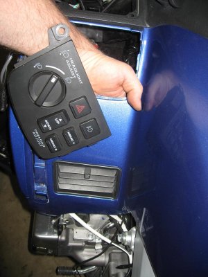
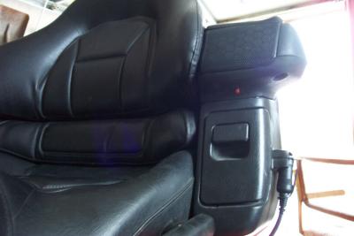
 Switch mounted in speaker pod on 2009 |
 Switch on 2009 |
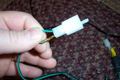 Inserting connector pins into connector body. Don't do this until you have the wire routed where you want it |
 Final switch assembly. Lets ride! |