


|
|
|
|
|
|
| fred harmon | profile | all galleries >> Galleries >> G Force Alarm System | tree view | thumbnails | slideshow |
| previous page | pages 1 2 3 ALL | next page |
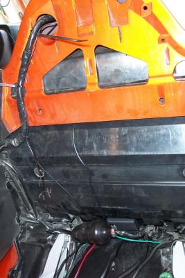
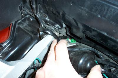 There is a hole on the right rear side of the trunk you can fish the harness through |
 Pull the harness through back to the turn signal connectors |
 Then just connect each set in series |
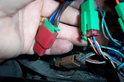 Second set connected in series |
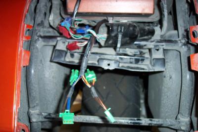
 All connections done for rear turn signals |
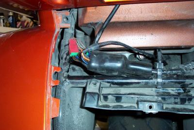 Now you have to stuff it all back into the boot. One connector wouldn't fit |
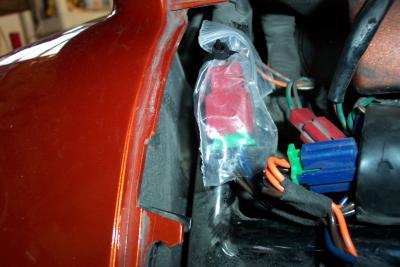 I wraped the loose connector in a small ziplock bag and tied the top closed |
 All connectors are now protected from the water spray of the rear wheel |
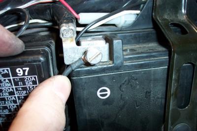 Here is the negative battery connection. Do the same for the positive side |
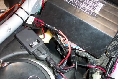
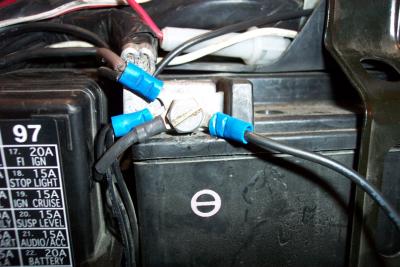 Here is what my negative battery connection really looks like with all my other toys hooked up |
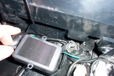
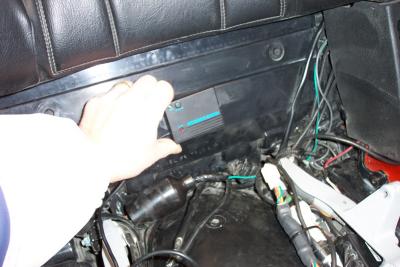 One possible location of Microwave motion sensor |
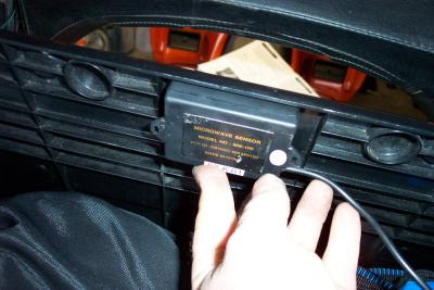 Instead, I decided to mount it INSIDE the trunk, facing forward. This position gives good response at the minimuim setting |
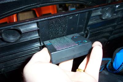 Again, I used Velcro to hold it in place |
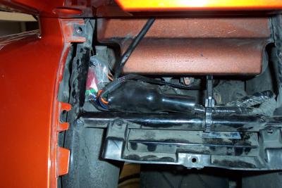
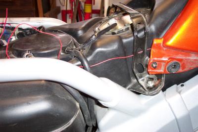
 I put the siren facing down underneath the right side frame rail, between the gas tank and rear fender |
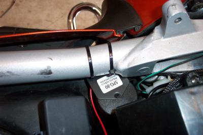 I used two zip ties to attach it to the frame rail |
 Here I used Velco on the Pager module (I just love Velcro) |
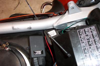
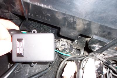 Locating pager module |
 Pager Module in position |
 I removed the passengar back rest (2 screws) and ran the pager antenna wire up into the top of the trunk for good transmission |
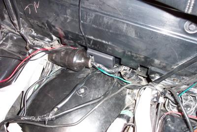
 Here are the alarm and pager wires connected. I choose to solder and heat shrink them |
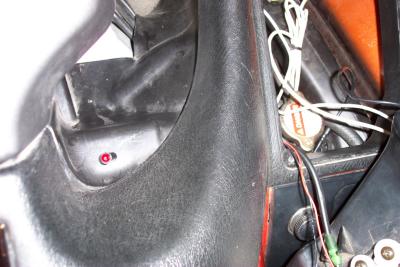
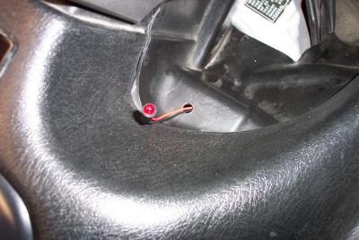 Location of flashing diode next to ignition on right side |
 Don't try to mount it on the left side like I did. There is something underneath the cover here that will block it. |
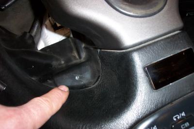
 I routed the wires over to the right side glove box |
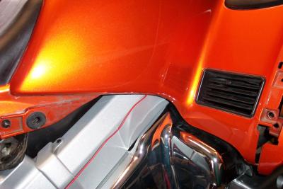 I then loosened one side of the top shelter and routed the red wire down. The black I connected to a ground point on the bike |
 I ran the red wire back along the tank back to the alarm box |
 Alarm installation complete |
| previous page | pages 1 2 3 ALL | next page |