


|
|
|
|
|
|
| fred harmon | profile | all galleries >> Galleries >> G Force Alarm System | tree view | thumbnails | slideshow |
| previous page | pages 1 2 3 ALL | next page |
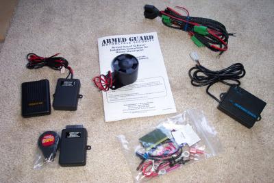 Here the kit, including pager, and perimeter options. MSRP $224.95 Distributed by Big Bike Parts and Electrical Connection |
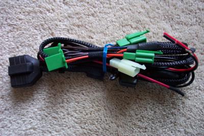 This is the wire harness to plug the G Force directly into the GL1800 with no splicing needed |
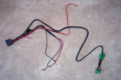 The large connector is for the alarm, and smaller connectors for starter and rear turn signal lights |
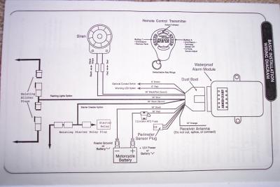 Connection Diagram shows how the system connects to the bike. |
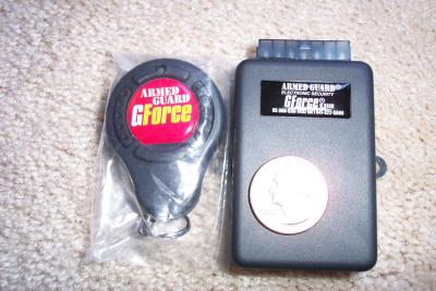 This is the alarm brain and remote |
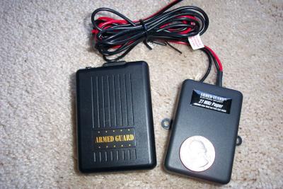 The pager option, which costs an additional $125. Range is up to 1 mile |
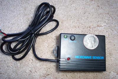 Microwave perimeter sensor option, $45 adjustable range to 10'. Selectable on/off feature with remote transmitter |
 Armed Guard point of contact |
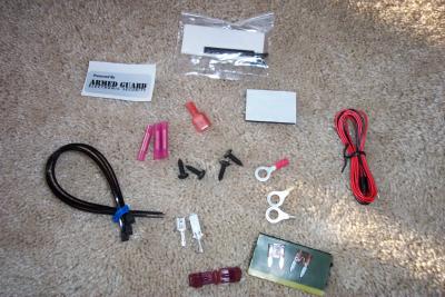 Supplied hardware for installation |
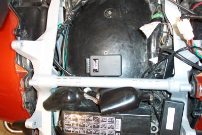
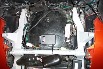 This is one possible mounting location. Due to my Mic-Mutes and Kennedy PTT hack, I moved it to a less crowded spot |
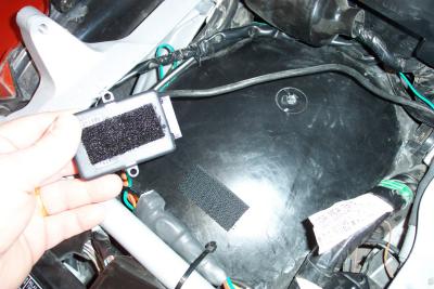 You can either Velcro or screw it in place |
 If you don't have Mic-Mutes, the unit will mount nicely agains the crossover support bar |
 I found a less crowded space on top of the gas tank. If you mount it here DO NOT screw it into the gas tank |
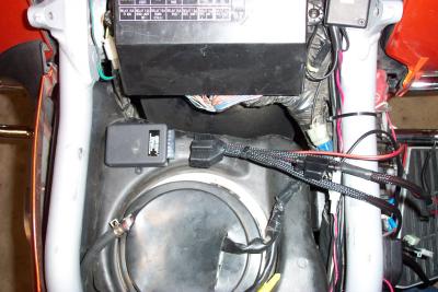 I used Velcro to hold it to the tank. DO NOT USE SCREWS INTO YOUR GAS TANK UNLESS YOU WANT A GAS LEAK |
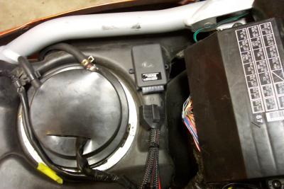
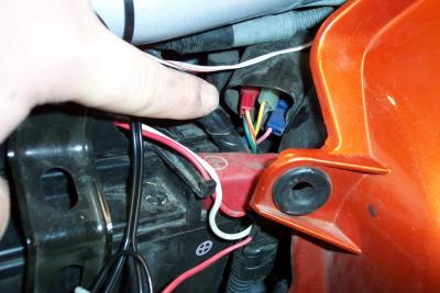 The starter connector is next to the battery. It is a red connector with a Green/Red stripe and a Yellow/Red stripe wire |
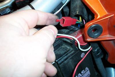 Here is the starter connector disconnected |
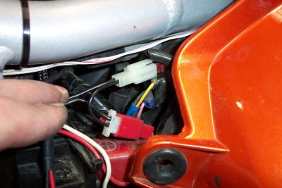 The alarm connectors plug into the starter connector in series |
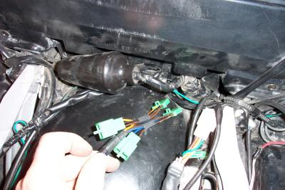
 I tucked all the connectors back into the boot to give them some weather protection |
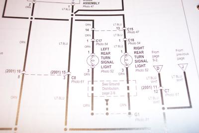 This is page 9-4 of the ETM. We need to locate connectors C17 and C18 |
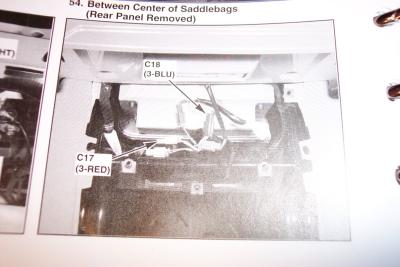 Photo 54 on page 12-8 of the ETM shows connector locations. |
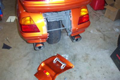 You have to pull of the rear panel to reach the rear turn signal connectors |
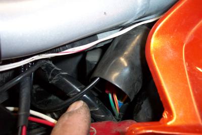
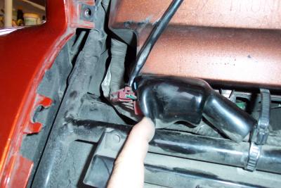 The connectors are inside this rubber boot |
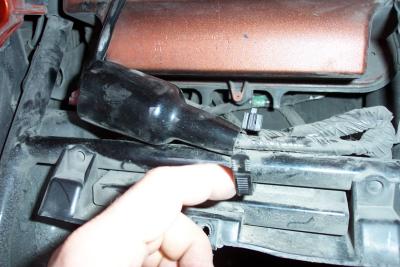 Release the zip tie so you can pull the boot back out of the way |
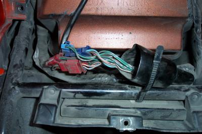 Connectors exposed |
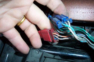 The two connectors we are after have three wires each |
 Now you have to fish the harness down under the trunk, between the rear fender |
| previous page | pages 1 2 3 ALL | next page |