12-SEP-2008
DIY guitar pedal power supply
For convenience, reliability and tone I built a nice ps unit that has several separate isolated regulated power supplies. If you've ever tried to power a lot of pedals at once it is a task fraught with peril. This PS scheme removes all the issues and can have a huge impact on tone.
Here's where I got started. Paul Ruby really knows his stuff.
Here's
R.G. Keen's Eight Legged Spyder PS schematic Paul links to. Paul mentions 10 Ohm current limiting resistors and 0.1uf ceramic caps. I left them out, but according to Paul, "I included a 10-ohm, 1W resistor between the output of the 7809 and 10uf output cap. Also, there is often a 0.01uf cap mounted directly to the 7809 between its output and gnd pins to avoid oscillations. As long as the 10uf cap is very close to the 7809 with short leads, the 0.01 is not needed. Same goes for the input side of the 7809." I also used 1000 uf caps instead of the 220 uf.
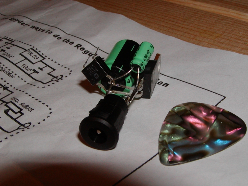
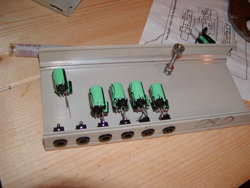
Rectifier regulator and jack
Tiny, short signal paths and each unit can be mounted with the regulator's metal side to a heat sink or to the side of the chassis. I didn't anticipate much heat for my application so didn't bother. You must mount the jack through the panel before soldering the rest of it to the jack, this is just for the purposes of the pic.
On the left you can see the two leads coming off the rectangular rectifier chip. Solder the leads coming from the transformer to these. They are very fragile but even after breaking a few off I was still able to solder the wire leads to the little nub that was left.
It's important to use plastic jacks, you don't want this part of the circuit touching the chassis as far as I know.
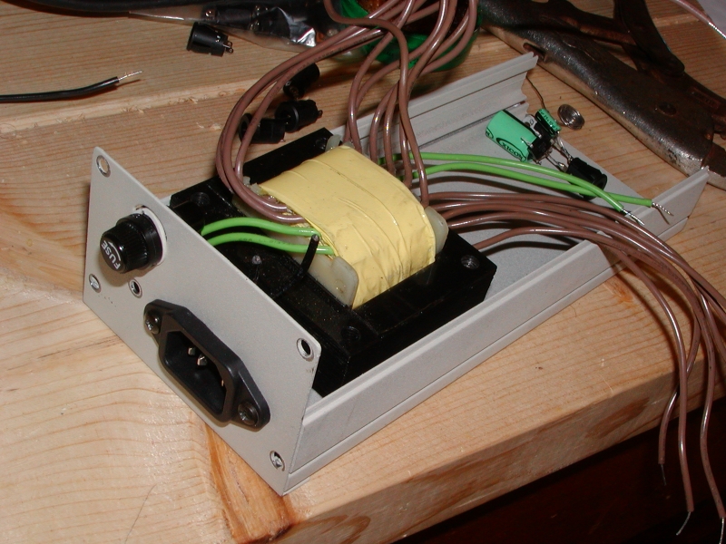
Transformer and chassis
I used the bottoms of two oddball chassis I had laying around. I used an air nibbler from Harbor Freight to cut the hole for the IEC connector. The transformer is $20 at the bottom of this page,
Weber VST tranformers
model WPDLXFMR-1 but there is also a 120/220/240v version. It has eight 11 volt, 300mA windings and one 9 volt, 2 amp winding. The 9v 2 amp winding is suitable to replace Line6 PX2 power supplies, just run the straight unadulterated 9vac for Line6 modelers like a PodXT or my beloved DL4 Delay Modeler.
Plan B was to start with a steel stud from Home Depot for the chassis.
You can combine two of the secondary windings in series to get 22v which you can regulate down to 18vdc or 12vdc or whatever other needs you might have. I have two 12vdc pedals but they use opposite polarities so I'm still not quite sure how I'll handle it.
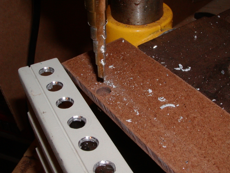
Drill the holes for jacks
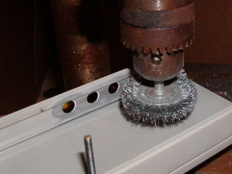
clean up holes w/ wire wheel
inside of chassis
The transformer fit so perfectly inside this chassis I only used one screw to hold it in place.
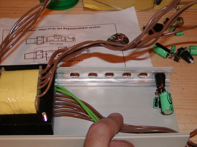
mounting the rect/reg units
The jacks snap in from the outside, THEN solder the rect/reg unit to the jacks. Careful, guitar pedals are generally tip NEGATIVE and I screwed it up and had to redo them all.
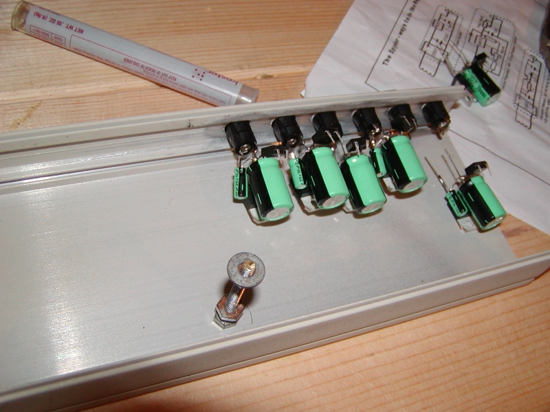
mounting the rect/reg units, jack side
11-SEP-2008
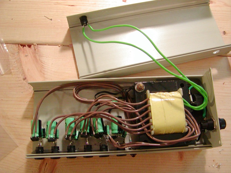
complete inside
The green leads are for the 9v 2 amp winding, I just left it AC for the Line6 stuff.
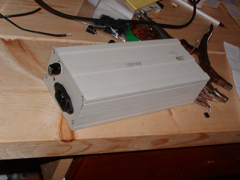
11-SEP-2008
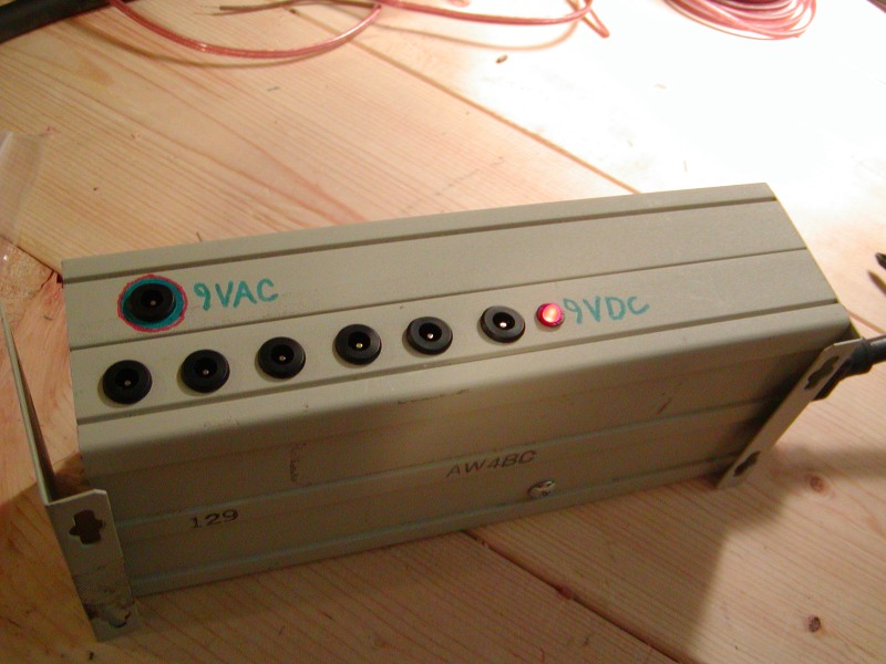
complete outside
Do yourself a huge favor and put an LED on there so you know if the unit itself is getting juice. I usually use a 1k resistor to control the brightness of the LED, I don't like them very bright usually.
I was tempted to make the 9vac jack some other type of jack to avoid accidents, but didn't bother in the end.
12-SEP-2008
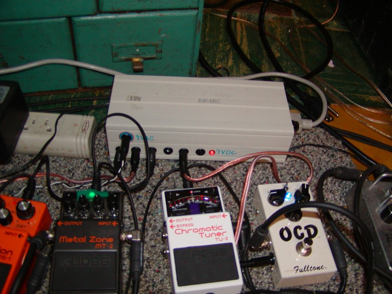
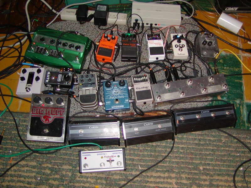
Happy pedals!
Here's the PS unit powering a plethora of pedals. The T-rex Roommate reverb and Eclipse both have tubes and both need 12vdc so I haven't gotten to that yet. I left 2 pairs of windings free that I plan cobine in series then rectify/regulate down to 12vdc which should take care of the Eclipse, but the Roommate's ps is 1.2 amps so I'm not sure if it will be ok running off my PS or not.