A hidden Screw ?
Underneath the Mode Dial you will
find another screw that holds the
Top Cover.
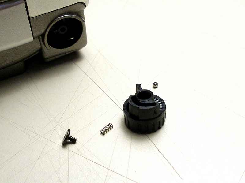
Do Not Remove
Don't do as I did by removing this
Diopter Adjusting Knob. The camera
can be removed from the rear case
by lifting up on the opposite end
and rocking it out. This is a bear to
reassemble. The little spring fits
down into a hole, the ball is placed
on the end of the spring, then the Knob
is placed over and retained with the screw.
That little ball has a mind of its own.
Jumps off the spring and hides. The last time
it hid for good and I never did find it.
So as a replacement, in my junk drawer was
a tiny ball bearing from my model building
days. I took it apart and found the balls
were the same size.
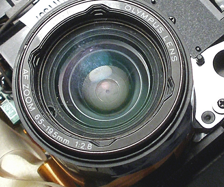
Close-up of jammed lens
If you look close you can see the opening for
the f stop. This shot is with the camera covers off.
Not a good picture, but
I am not going to take this camera apart again for
anotherpicture. Anyway down in the recess
(maybe 3/8 inch deep)is a place where you have to
remove/reassemble a very tiny screw. My old
Tool Design/Toolmaker past helped here. I used a
piece of shrink tube "shrunk" about the head of
the screw and the shank of the Phillip's Jewelers
screwdriver.Worked like a charm.
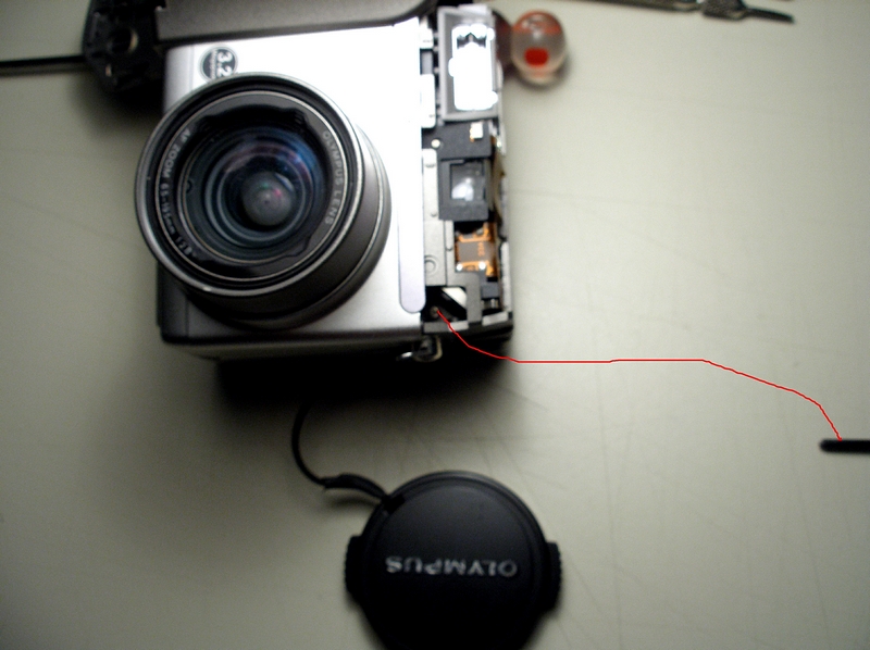
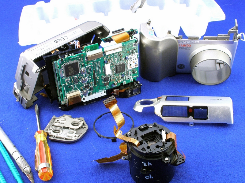
C-3020z with the covers off.
Now here is where you can get a shock.
This little camera has bit me twice.
Note in the area where you see the color wires,
This is the area for the capacitor for the Flash.
KEEP your fingers off this area. Not a pleasant feeling.
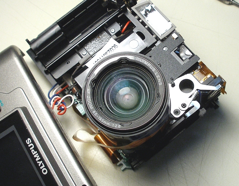
Another view of the dis-assembly
This shot is when I had tore down the
entire camera. Note the lens housing
sitting in the front.
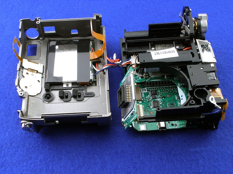
Almost ready to mount the Sensor Circuit Board.
This Sensor Circuit board is mounted to the rear
of the Lens Barrel assembly. Then the two halves
of the lens barrel will be held together.
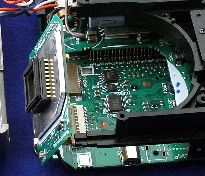
Another view of the Sensor Circuit Board
This view to show the sensor mounted
to the circuit board.
Another View of the Sensor Circuit Board.
After the Sensor is mounted to the rear of the
lens barrel assembly, this composite assembly
will be mounted back into the camera body. The
camera back will be rotated for assembly.
Note! at the top of the camera body. You can
see right under the knob, part of the battery
case. The other half is on front part of the case.
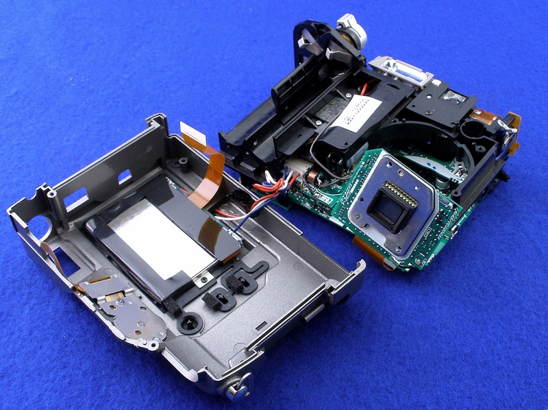
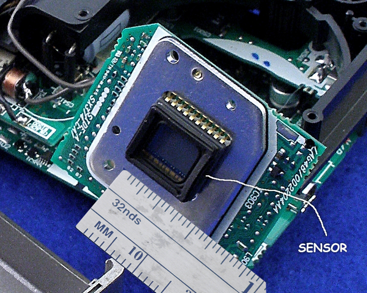
A close up of the Sensor.
I find it very mind boggling after looking at
the size of the sensor, that we get such clear
pictures at a very much expanded size.
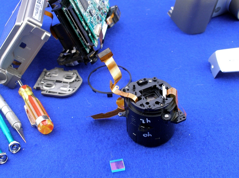
Lens Housing removed from camera.
Note!
The little glass part in the foreground
is the IR filter. Without it and a piece
of plain glass in its place I would have
a dedicated IR camera.
Lens Housing with the Sensor removed.
The little gear on the right hand
side of the housing is jammed. This
gear meshes with the gear on the
camera motor.
Note! the IR filter fits into the
Rectangular opening on the back of
the lens housing and is held in place
with the Sensor and its circuit board.