This old format has run its course and the new site is now up and running. Articles here will no longer be kept current, or up to date. Eventually this site will go the way of the buggy whip. If you see this "WARNING" image, the article has been moved, updated and may have more added to it than you will find below.
IMPORTANT: If the first image of the article below features strikethrough; strikethrough it means updates or edits have been made and we are urging you to visit the new site for more current information.
Please change your bookmarks and please visit the new site. See new links below.
PREFACE: This article is long and rather detailed. It is written in two parts and covers crimp tooling, terminal selection, types of terminals and includes plenty of do's & don'ts. The first part covers heat shrink terminals and then goes over insulated terminals.
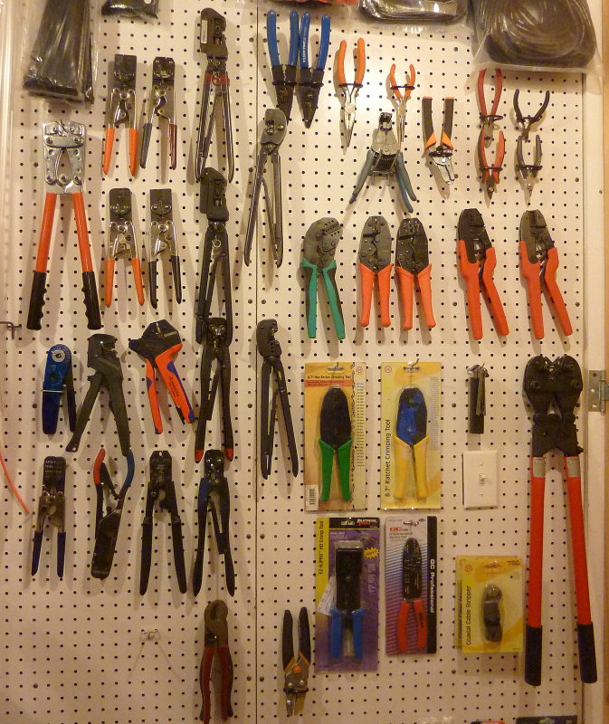
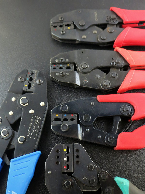
After writing this article I have had many request to know what tools I actually use. This is about it...
The tools on the left hand side are my primary hand tools. They are:
AMP = Seven tools total - These are all guillotine style tools, jaws come together vertically not like scissors.These tools are for Red, Yellow & Blue insulated/PIDG & "F" type open barrel terminals. These tools are the GOLD STANDARD, cost HUGE money, and usually only do one or two sizes per tool... (ouch!)
Rennsteig = Orange & Blue handle - This is a high quality German made guillotine style tool that I use for red, blue & yellow butt splices. I also have dies for solar MC-4.
Molex = Three tools for pin & socket style connectors either waterproof or non waterproof. I use these for assembling field install waterproof connectors for radar, Espar heaters etc. etc...
Hollingsworth = This is a tool that I modified to use for heat shrink 14-16GA butt splices & brazed barrel heat shrink 14-16GA ring terminals. NOTE: This tool was not designed for heat shrink but in testing out performed my heat shrink specific dies.
Anderson = This is a tool that I use for 10-12GA heat shrink butt splices & brazed barrel heat shrink 10-12GA ring terminals. NOTE: This tool was not designed for heat shrink terminals but in testing out performed my heat shrink specific dies.
Daniels = This is a tool I use for multi-pin plugs that use this type of pin crimp.
PM Hand Tools = A Swedish made parallel style tool I use for crimp solder style PL-259 VHF connectors.
The tools still in packages are tools I use less often or where the specific die information is on the packaging and it is just easier to keep the package. I also did not list any of the mid grade tools. Those are just to $200.00 to $1800.00 tools.......
When you are thinking $50.00 is a lot to spend on a tool consider that that wall contains about $6000.00 worth of crimp tools and dies......
Crimping is a form of wire termination used the world over and is the number one method used. It is used in everything from the automotive market, aerospace, military, NASA, industry and even in nuclear power plants. Done correctly utilizing the proper tools crimping is extremely reliable.
MARINE WIRE TERMINATION
There are a few key points with crimping for the marine environment:
#1 To create a proper cold-formed termination between the terminal and wire
#2 To use tools and terminals that result in consistent & easily repeatable terminations
#3 To use wire and terminals that can handle the marine environment
#4 To produce terminations that don't result in high resistance
#5 To choose terminals that are made from tin plated copper not aluminum
#6 To choose tools that allow for a repeatable crimp before releasing
#7 To use proper technique which will result in a reliable time tested and proven termination
The Good, The Bad & the Ugly of Crimpers
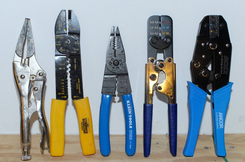
In this photo I have lined up a short selection of wire crimper's. The one on the far left IS NOT A CRIMPER! I only say this because I have witnessed people putting together marine terminations with a pair of PLIERS.
The next crimper, the one with the yellow handles, is a cheap hardware store quality crimper and should only ever be used in an absolute emergency.
The middle tool is a low grade Klein strip & crimp tool though it's not really well suited for much other than crimping non-insulated terminals and stripping wire.
The fourth tool is a good quality DIY grade crimp tool intended for heat shrink crimp terminals. This one is a CMI product & is a Taiwanese made version of the AMP 55893-1(LINK) tool and runs considerably less than half the cost. Sadly this AMP tool used to be made in the USA and apparently no longer is. Even FTZ, a tool I used to sell, that was made in Taiwan, is now "Made in China". The Taiwanese made crimp tools are generally considered a better quality than mainland Chinese tools are.
The CMI version is actually a better quality tool IMHO. This tool is designed specifically for crimping marine or aviation grade heat shrink terminals. The jaws of this crimper are fairly well machined, and wide enough in cross section, to produce a decent quality crimp. This crimper is also of the controlled cycle or ratcheting type and will not release until a proper crimp has been made.
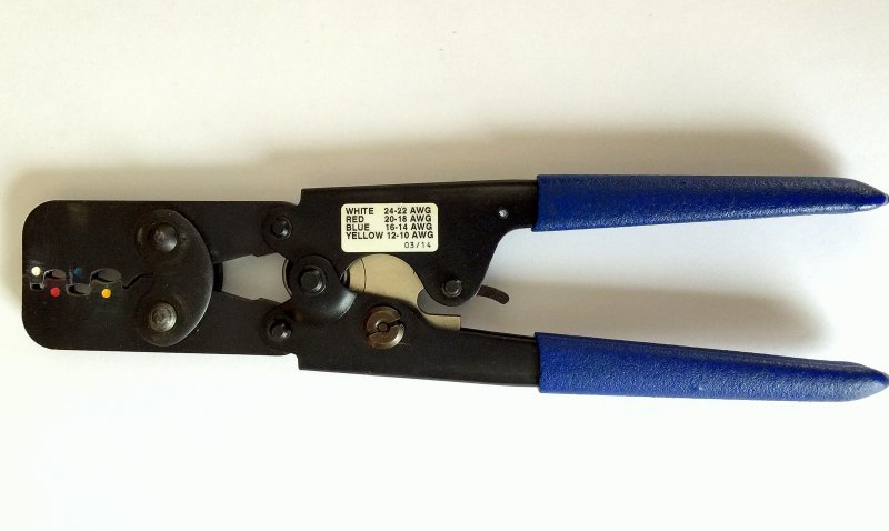
The final crimper shown is another ratcheting type crimper but this one, set up with the jaws shown, is designed for insulated crimp terminals. It makes a "double crimp" for insulated terminals.
Read on for more details on these different crimpers.
NOTE: There is no such thing as a "marine grade" terminal. I refer to "marine grade" only because that is what the retailers tout them as and what most boaters know them as. "Marine Grade" is just a high quality insulated or heat shrink crimp termination. The same terminals are sold into aviation, industry and marine applications. In aviation they are often referred to as aviation grade... The difference with aviation terminals is that they need to meet minimum standards and be crimped with "certified" tools all of which are FAR MORE EXPENSIVE than the average boater is willing to buy. I personally & professionally use aviation certified tools but the ones below will get you you to better than average...
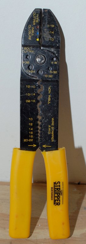
A Good Example of a BAD Crimper
This is an excellent example of a bad crimping and stripping plier. I say plier because I really can't bring myself to calling this a "tool". These hardware store quality crimp-n-strips will deflect, flex and even cut the heat shrink on expensive heat shrink terminals thus defeating the purpose of spending good money on great terminals. The make horrible terminations, meet no standards and you truly get what you pay for.
The biggest worry with el-cheapo crimp tools like this is the lack of pull out tensile strength you can achieve due to the very narrow cross section or thickness of the jaws. They also lack any sort of reliability in repeatable crimping.
The industry standards for determination of termination quality, including the ABYC, NASA, US Military, UL and other standards organizations, is a tensile strength pull test. This tool does not fair well here....
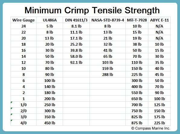
Crimp Tensile Strenght Standards
People ask me all the time, "How do I know if I got a good crimp tool?".
The only way to know is to physically test your crimp terminations with your tool and your terminals. When you find a combination that meets or exceeds MIL-T-7928G then you have an excellent combination. Once you find and have tested all the combinations YOU USE stick with that brand of terminal and tool ALWAYS.
Unfortunately this is the ONLY decent way to properly know your tool is going to result in a termination suitable for holding up to the marine environment.
After many years of testing, and using tens of thousands crimp terminals in the marine environment, I can say without pause that MIL-T-7928G, for me, is the BARE MINIMUM tensile strength I want to achieve. If you are frugal in your tool and terminal choice then you should at the bare minimum strive for UL-486A.
"But RC what about the ABYC E-11 standard?" My 2� on the ABYC E-11 tensile strength standard is that it is PATHETIC and you will be a chronic under achiever if you set the bar to the PATHETICALLY LOW ABYC E-11 tensile strength guideline. E-11 is a complete joke in this regard. There I said it.....! (wink)
Please note that I am a current ABYC member/supporter and also an ABYC certified technician. Just because I am an ABYC member and certified tech DOES NOT mean I have to agree with everything. I call it as I see it and the ABYC E-11 TABLE XV - TENSILE TEST VALUES FOR CONNECTIONS is a ridiculously LOW bar to set......
This is a chart I created by comparing all the useful standards for tensile crimp strength. The chart breaks out the varying crimp standards, including the pathetically low ABYC E-11 standard.
It should be pretty easy for any good quality terminal and mid level or better crimp tool to EXCEED MIL-T-7928G.
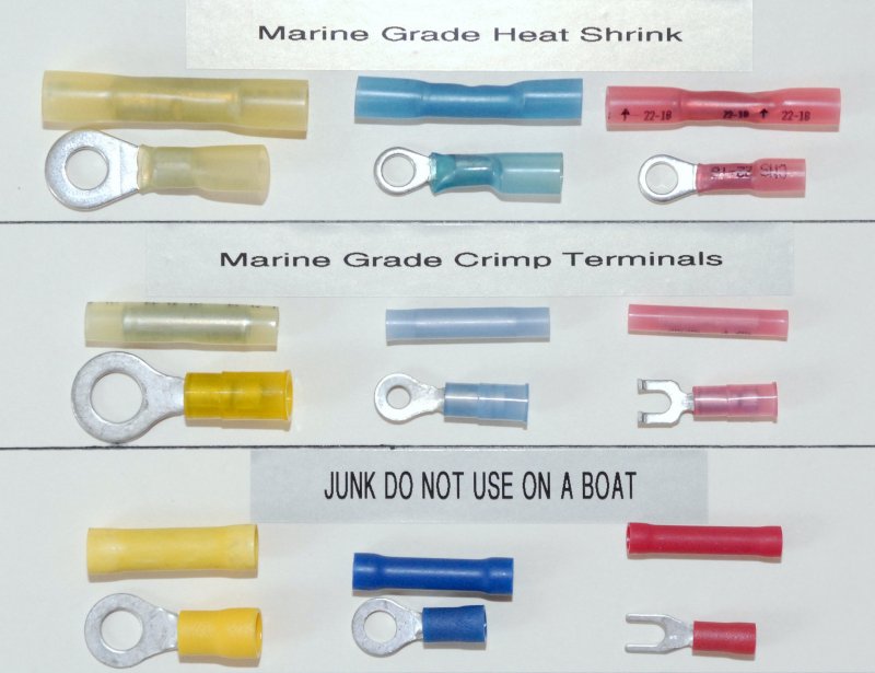
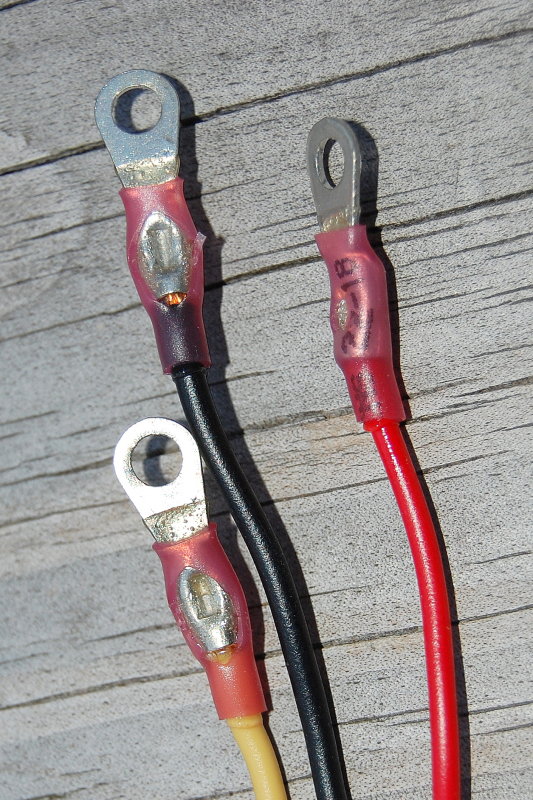
Crimp Terminals - Optimal to Sub-Optimal
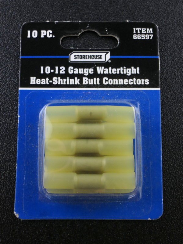
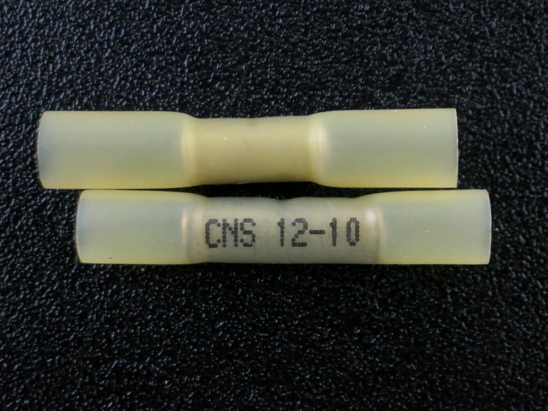
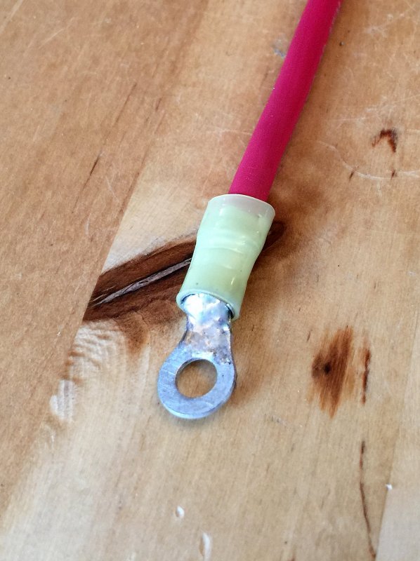
This photo shows a few of the different types of crimp terminals you can purchase. The terminals in the top row are marine grade crimp connectors with built in adhesive lined heat shrink and are the best possible solution, for most applications, to use on a boat.
As I mentioned there is no such a thing as marine grade terminals but that is what the better quality terminals have become known as. Heat shrink terminals, as seen in the top row, are expensive, but in my opinion almost always well worth it. They are available from manufacturers such as Ancor Products, AMP, and FTZ.
NOTE:When choosing crimp terminals I would urge you to buy from companies with a reputation to uphold and a long history for quality. If you buy from companies such as AMP/Tyco, Molex, FTZ, Burndy, Thomas & Betts (T&B), 3M, Ancor etc. and you will get better quality terminals than the cheap no-name junk that has infiltrated the country over the last 20 years or so.
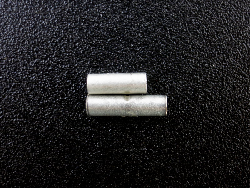
The second row of connectors are called insulated terminals but are not heat shrinkable. The ring terminals are a what are considered a three-piece terminal and the butt splices are a solid tube with no seam. These terminals stand head and shoulders above the bottom row but keep in mind that they are not sealed connections. As such they are quasi-open to the marine environment. When used in conjunction with UL 1426 tinned marine grade wire these crimp terminals will last a long, long time provided they are not in any direct contact with water, such as in a bilge.
The third row represents Wal*Mart or Harbor Freight quality terminals that should be avoided on a boat. Heck I'd not personally use this crap in a child's tree-fort let alone a boat. Perhaps the biggest issue is that, being of the bottom feeder variety, they tend to vary tremendously in ID and OD and as such it is a crap shoot as to how a crimp will turn out.
A good tip when buying connectors is this; if you can't see through the insulation, it's most likely vinyl, and should really be avoided. The vinyl insulation on this type of connector can and will crack and the raw metal thickness, where the wire meets the connector to be crimped, is very, very weak in comparison to top quality terminals from reputable manufacturers such as those listed above.
For non heat shrink insulated terminals I use AMP PIDG Terminals and buy them where ever I can find the best price. Because they are AMP they are quite expensive so I search around......
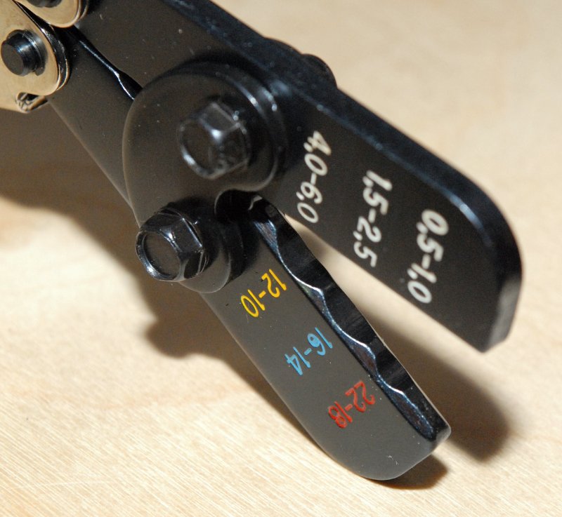
Heat Shrink Termination - A Heat Shrink Terminal Crimper
This crimp tool is designed specifically for use with heat shrink terminals. While certainly not a super pro-level tool it is a decent mid-grade or DIY level tool for the money. This tool is far better than using the wrong tool on these expensive terminals.
This tool is designed to not damage the heat shrink and will yield a reliable crimp when used on factory made heat shrink crimp terminals.
This particular tool is made in Taiwan by a company that makes tools for many of the big names. For readers of this site I was able to strike a deal with an importer and I can now sell this tool for $46.95. All purchases of this crimp tool help to keep MarineHowTo.com FREE!!!
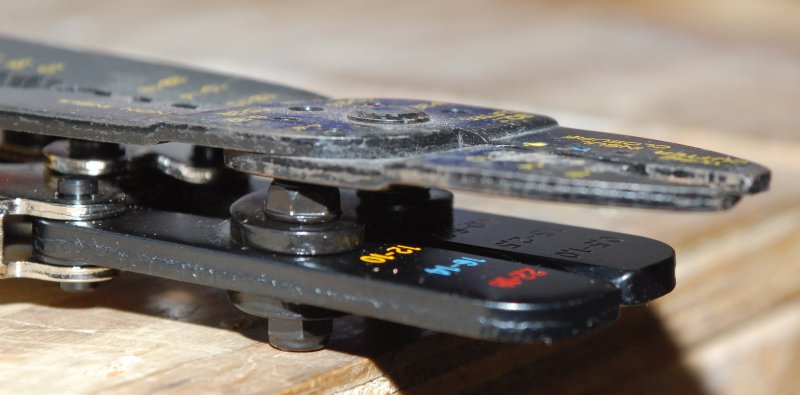
This should illustrate why not to use cheap crimp tools. The bottom tool is the CMI controlled cycle heat shrink crimp tool and the top one is a standard $12.00 cut, strip & crimp tool which certainly does none of it's intended uses well at all.
The thicker well machined jaws of the CMI heat shrink crimp tool will yield a significantly thicker crimp band and lead to a better cold formed crimp.
Well Machined Jaw Faces
A smooth well machined jaw surface is important when working with expensive heat shrink terminals. This tool is designed to avoid molesting or damaging the heat shrink where a cheap or incorrect tool will damage it.
WARNING: No crimp tool for heat shrink terminals that I know of will reduce the occasional tear in heat shrink to 0%. You will occasionally tear a heat shrink terminal no matter what heat shrink tool you use. The proper tool for these terminals greatly minimizes the risk but does not entirely eliminate the risk and make it 0%.
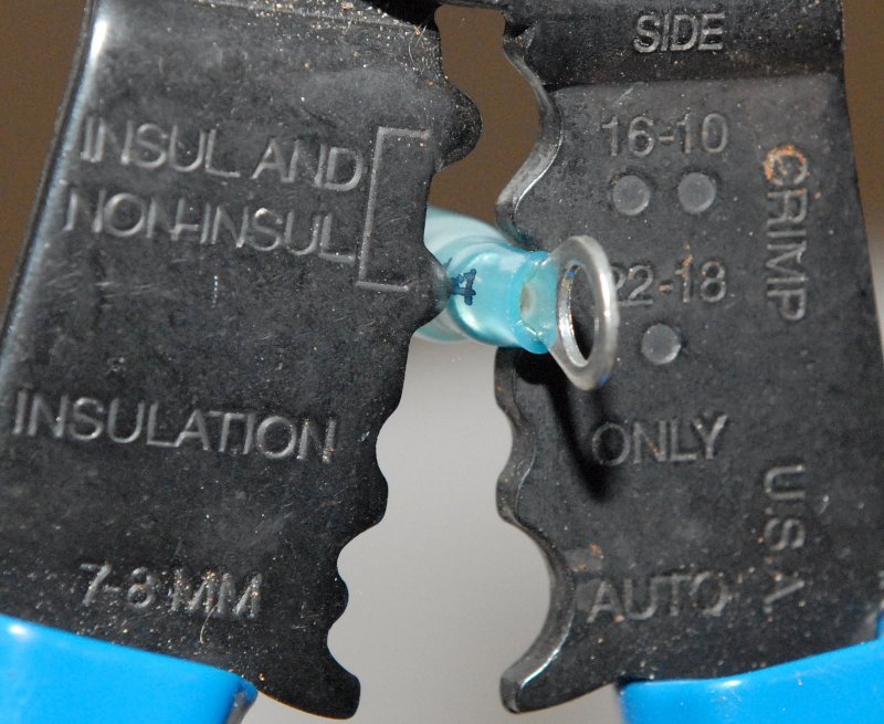
Dimple Crimper = Poor Choice
In this photo I have placed a heat shrink terminal into the jaws of a Klein dimple or staking crimper. It certainly does not take a rocket scientist to understand why a dimple crimper should be avoided for use on a heat shrinkable terminal. Once you squeeze the grip the dimple can puncture the expensive protective heat shrink insulation thus rendering the protection you paid for virtually pointless.
NOTE: This Klein cut-strip-crimp tool shows a spot for insulated crimps and also says insulated & non-insulated for the dimple crimp nests. I can not, with a good conscience, recommend anyone using this particular tool, or any crimp tool like this, on heat shrink insulated terminal.
Using a one size fits all, crimp tool will usually not save you any money in the long run.
IMPORTANT: If and when you do use a dimple/staking crimp tool the dimple is ALWAYS MADE OPPOSITE THE SEAM. Always face the seam AWAY from the dimple, not at it, as I have shown.
In this photo I am showing the orientation many folks often use, it is incorrect. Doing this can split the brazed seam and cause the termination to fail at a very low pull out strain. If you must use a dimple type tool the dimple should be be made opposite the seam.
Perhaps the most lacking feature of a dimple or staking crimper is that you lose any sort of strain relief crimping on standard insulated crimps. The entire load is taken by just the crimp barrel.
A double-crimp ratcheting tool is designed to make two crimps, one for strain relief, which has different sized dies, and one for the bare wire crimp. If you are trying to wire a boat to be ABYC compliant, which by the way is not a requirement for a DIY, a dimple or staking crimper would not qualify as the correct tool to use under E-11 for insulated terminals.
Not The Right Tool For The Job....
This is a prime example I came across that illustrates exactly why it is important to use the correct tool for the job.
These expensive heat shrink crimp terminals were destroyed by the installer by using a staking or dimple crimper as opposed to a tool specifically designed for heat shrink terminals like the CMI Controlled Cycle Heat Shrink Tool. These terminals were less than a week old and the split insulation was intentionally hidden from view, but I found them.
Don't Be Fooled By Cheap Connectors
Don't be swayed by a cheap price on crimp connectors. A good quality crimp terminal will be made of tin plated copper, not aluminum. As I mentioned above FTZ, Burndy, T&B, AMP, Molex etc. all make good quality insulated and heat shrink crimp terminals, so you don't necessarily need to buy them at West Marine.
As an example, I buy 100 FTZ Crimp'N Seal adhesive lined yellow ring terminals from my distributor for about $70.00 per 100 so my guess is that you should be able to find them for less or slightly more. West Marine sells 25 Ancor terminals for about $32.00, or about $128.00 per 100.
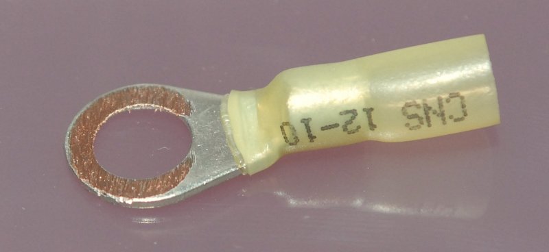
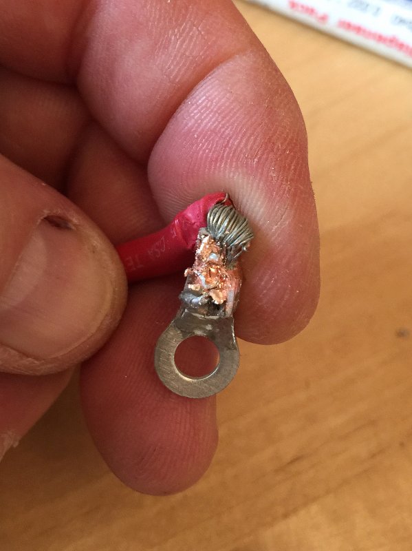
Real Copper !
OK, So I've ruined a few connectors for the sake of illustration, but, I did this to show what you should find beneath that tinned surface. I simply ground away the tinned coating to reveal the solid copper.
Harbor Freight Heat Shrink Crimp Terminals
I found these on a customers boat then pulled an FTZ heat shrink terminal out of my assortment bin and handed it too him. He took the HFT terminals and tossed this entire box into the trash.
Of course doing what I do for a living, I grabbed them out of the trash to use in this article. Cheap almost always comes at a price.
Harbor Freight Top - FTZ Crimp 'N Seal Bottom
No I am not kidding..... Are they really saving that much money by shorting you on a few tenths of an ounce of copper..? Compare the metal of butt splices in terms of length. Heck the jaws on my high quality Pro-HST tool are wider than the area Harbor Freight has left you to crimp to.
I Removed the Insullation
A few things things I noticed right away:
#1 The insulation on the HFT terminal came right off and really had little to no adhesive properties.
#2 The FTZ Crimp 'N Seal terminal fought me the entire way of removing the insulation.
#3 The FTZ terminal was more robust.
#4 The OD and ID of these terminals are not the same either.
HFT OD = 5.36mm FTZ OD = 5.52mm HFT ID = 3.69mm FTZ ID = 3.38mm
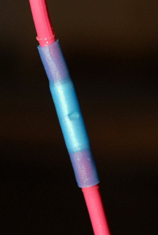
Making A Heat Shrink Termination
This picture illustrates a crimped then heat sealed butt splice crimp. Read on to see how this was done.
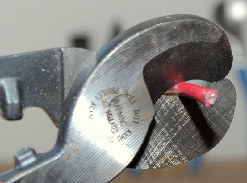
First Make The Cut
This is fairly self explanatory. My only suggestion here is to use decent wire cutters similar to the ones pictured. In this photo I've chosen a pair of Klein High-Leverage Cable Cutter's Part No. 63050. They cost about $20.00 at Home Depot & Chanel-Lock also makes a set that are slightly less money but they do a rather sloppy cut in comparison to the Klein. The right tool, for the right job, is always well worth the expense.
Using a set of Diagonal Cut Pliers or "Dykes" as they are normally called will not make as clean or as nice a cut as a good set of cable cutters will and will not work very well at all as the wire gauge gets bigger. I can cut up to 2/0 battery cable with these Klein cutters.
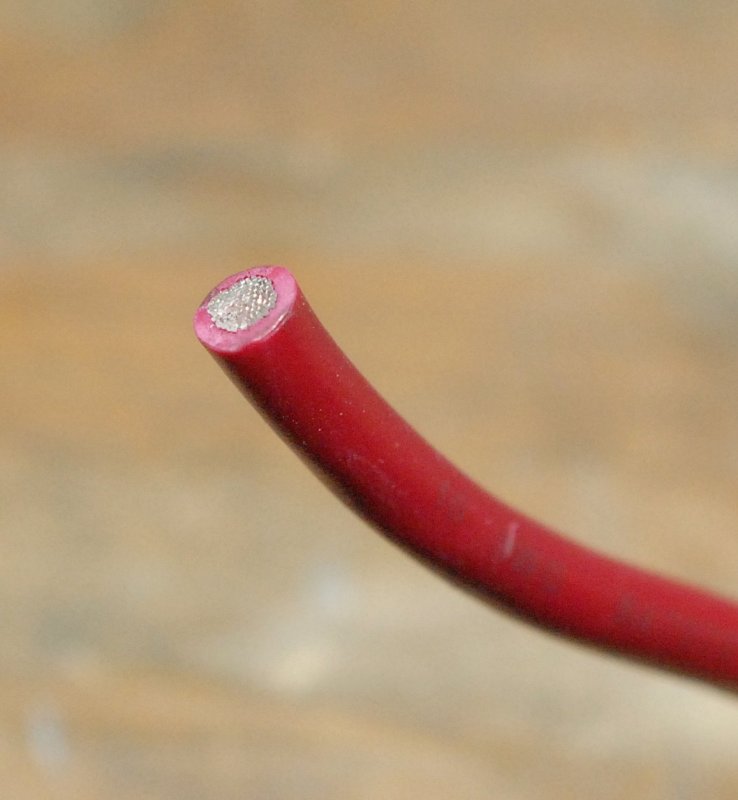
Examining The Cut
As you can see the Klein High Leverage Cutters make a beautiful cut. A good clean cut is one that will strip well and then slide into the terminal with no "stray" wires..
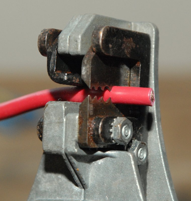
Strip the Wire
For stripping the wire I use the Ideal Stripmaster Part No. 45-092. There are many strippers that will work, and also that sell for less money, but the most important thing to consider is how carefully you strip with them.
It's somewhat important that you do not nick the wire or remove any strands when stripping. The blue Klein crimper/strippers I showed earlier are also a decent DIY quality stripper, but not as easy to use. They are also not as easy to get a consistent strip with without damaging some of the strands.
The Ideal Stripmaster 45-092 is one of the most reliable tools I own. I own a few of them and one of them I've owned since the early 90's. That tool has literally made thousands and thousands of strips and I can't tell which one is twenty years old and which one is 5 years old. Keep it oiled/lubed and clean, easier said than done working on boats, and they will perform well for decades.
When using the Ideal Stripmaster please be aware of the AWG and SAE markings on the stripping dies. If using AWG wire, as we should on boats, be sure to use the AWG slot for the wire gauge you're using and not the SAE slot.
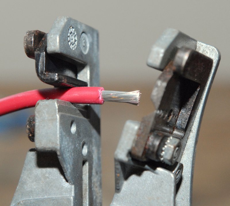
Which ever stripper you use, always examine the wire after the strip to check for strand damage. If the wire will carry any sort of high load you'll want a good clean strip with all strands intact..
Stripped
With the Ideal Stripmaster all you do is set the wire you your desired strip depth, usually about 5/16 of an inch, and squeeze. They make beautiful and repeatable strips every time.
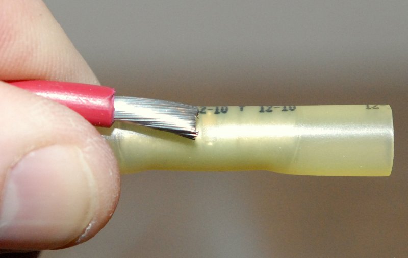
Checking The Strip Length
When using butt splices compare the strip length to the terminals depth. Most quality butt splices will have a stop or detent to denote the insert depth. If you look closely at this image you'll notice the center dimple on this butt connector. The wire should go as deep as the center dimple.
A Dry Fit To Confirm Strip Depth
Insert the stripped wire for a dry fit test. As you can see the red of the wire jacket butts right up next to the metal of the butt connector. This wire has been stripped to a satisfactory depth.
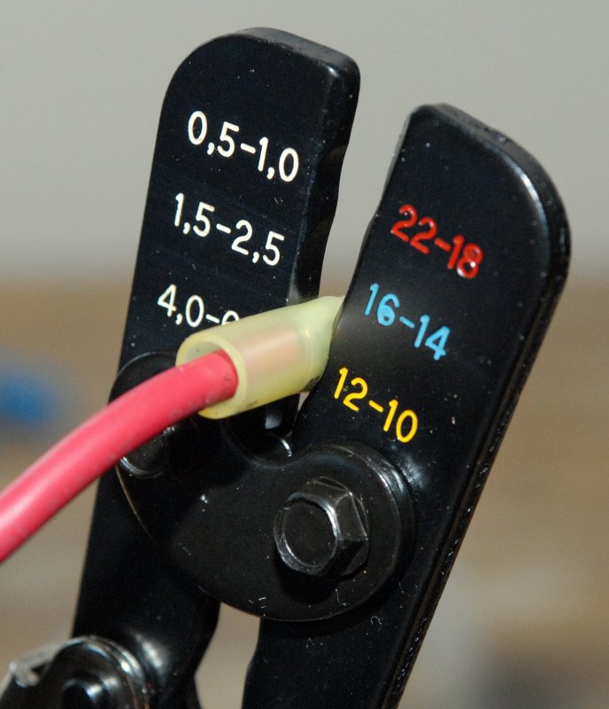
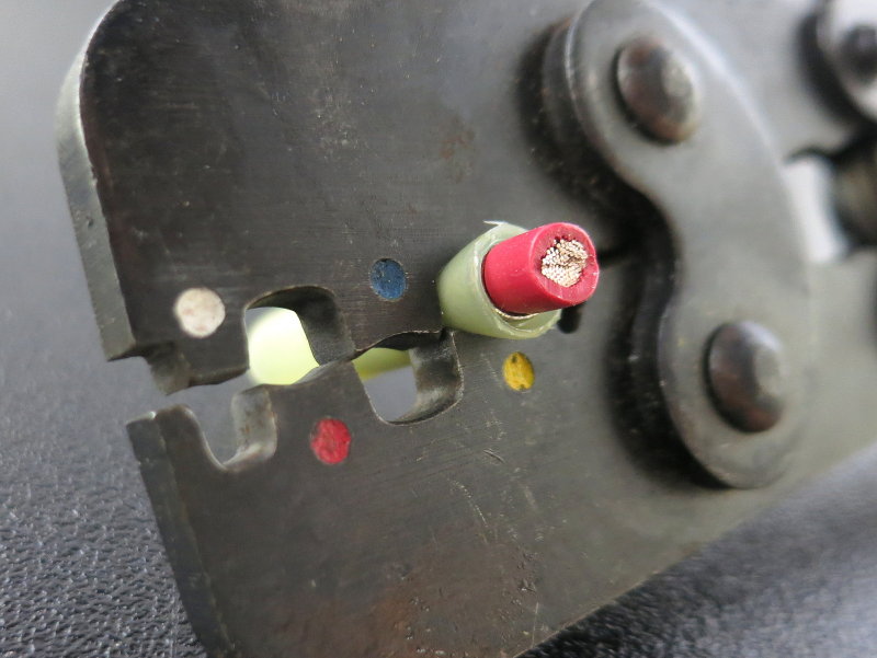
Making The Crimp
To make the crimp insert the terminal, centering the jaws over the barrel, and then tighten down slightly to about the first ratchet click. This will hold the terminal in place so you can then insert your wire. Once the wire is in, and properly seated, continue squeezing until the ratchet mechanism on the crimper releases. The ratchet mechanism of this crimp tool will not release until the crimp has been properly executed.
Almost Done
The ratchet mechanism has not yet released but it soon will and the crimp will be done.
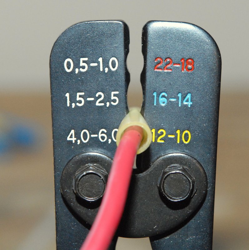
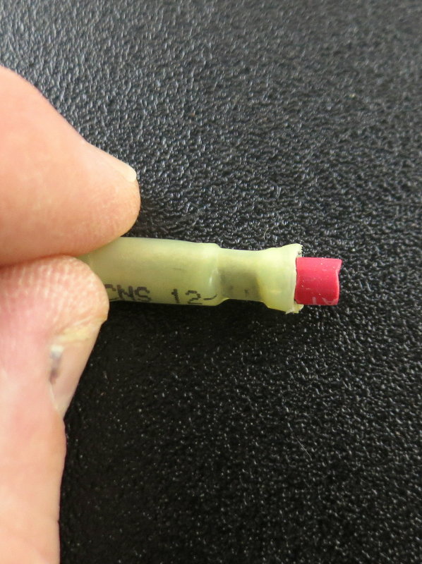
The FTZ Tool Completed Crimp
Here you can see how the completed crimp looks before any heat has been applied to the heat shrink.
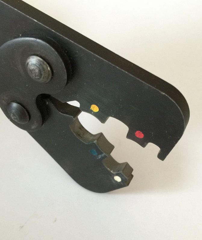
Pro-HST Tool
This is the Pro-HST crimp tool for crimping heat shrink terminals and this is the tool I use personally for heat shrink terminals. The crimp band is wider and the crimp nests are narrower providing and better cold formed crimp than the typical oval nest of the FTZ tool. While both tools work well this is the tool I choose for heat shrink terminals.
NOTE: I cut the non-shrunk end off of this terminal for illustrative purposes only.
The Crimp Band Is Very Wide
On reason the Pro-HST tool can perform so well is in the overall width of the crimp band which means more cold formed wire to terminal interface.
If you are a professional, interested in an excellent heat shrink crimp tool, I also sell this tool for $146.95 at the link below. All proceeds are re-invested into this site to keep it free.
As can be seen the width of the crimp band when using the Pro-HST is considerably wider and this leads to a better performing crimped termination.
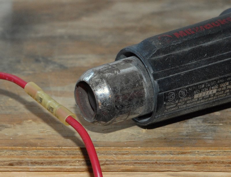
Heat Shrinking
Once you've completed the crimping it's time to melt the adhesive lined heat shrink. I am using my heat gun in this photo but not on the highest setting. I've found that with adhesive lined heat shrink you can melt it too fast and not get a proper adhesive melt on the adhesive lining. A slower melt will produce better adhesion of the insulation to the wire jacket.
TIP: Please do not use open flame on these expensive terminals. It leads to uneven melting of the adhesive, distortions in the insulation and can lead to leaks. Use open flame only as a last resort. A heat gun with consistent predictable heat is the proper tooling for these terminals.
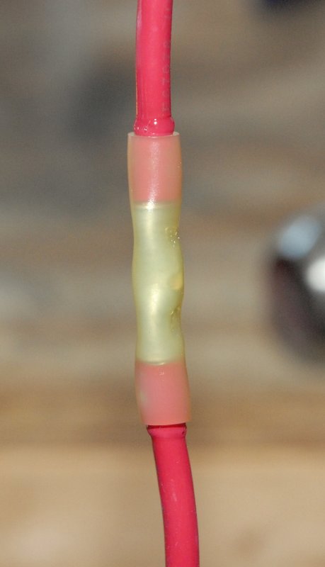
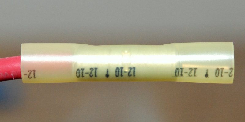
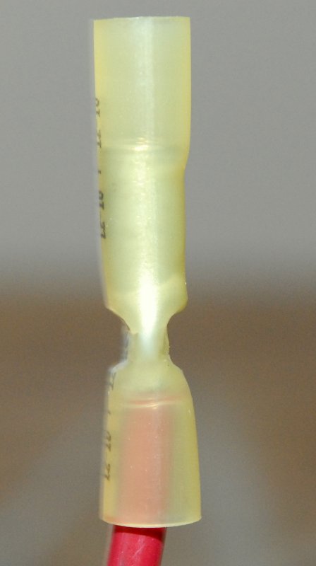
The Completed Butt Connector
Here you can see the clear melted adhesive lining squeezing out the ends of the insulation. With this type of crimp connection the transparency tells the story.
Where the heat shrink covers the wires jacket, and the barrel, your looking for uniformity in color and transparency. Any spots or areas that are a different color will be spots where the adhesive lining did not properly melt.
One other thing to take notice of is that the single ratchet crimp tool did not rip the heat shrink tubing.
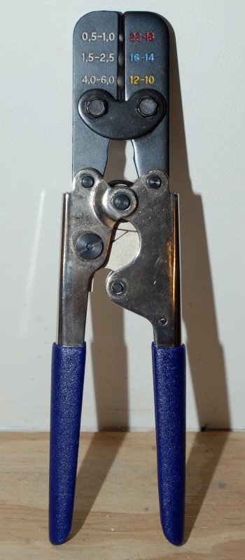
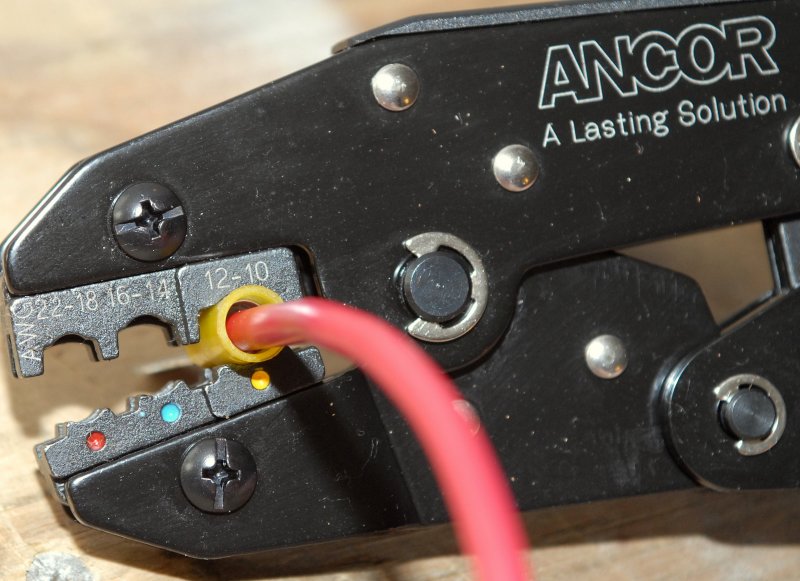
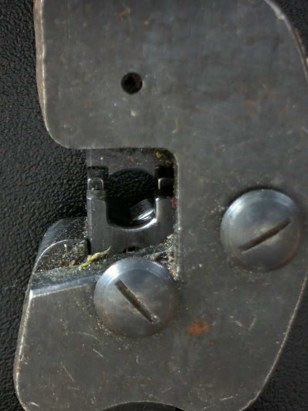
Making An Insulated Terminal Connection
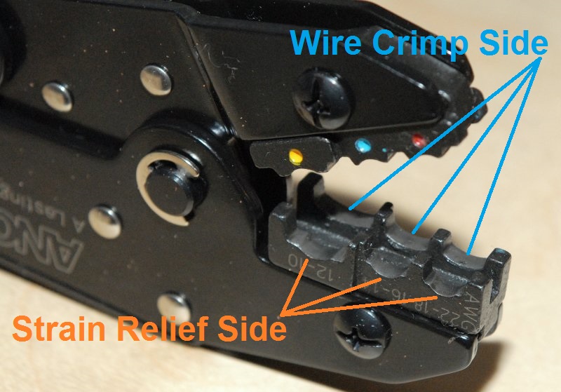
This is an Ancor double crimp ratchet tool for use with insulated terminals that are non-heat shrink. When crimping an insulated terminal, with a double crimp tool, it is important to note the direction the terminal is place into the crimp nest. The insert end or the end of the terminal which you feed the wire into, should always face the strain relief side of the crimp die.
Remember when I said "double crimp" yes, this tool makes two crimps at the same time. One crimp for the wire and one crimp for strain relief. These two sides of the crimp die are not symmetrical. The side where the colored dot is, on this particular Ancor tool, crimps the strain relief portion of the terminal and the other side crimps the wire end.
If you make a crimp with the wrong side of the crimping tools die, the crimp will not be correct and will likely fail.
TIP: Other double crimp tools from other manufacturers, may be different than this tool. Examine the dies or check with your tool manufacturer for instructions. The side with the smallest crimp ID is the one to crimp the bare wire end.
WARNING: Double crimp tools are UNIDIRECTIONAL! If you crimp the terminal backwards it will pull out far to easily and pose a safety risk. The strain relief crimp nest is considerably larger than the crimp nest designated for the bare wire. A fair number of readers have complained that their double crimp tools don't work well, and some cheap Chinese "look-a-like" tools may not. I always explain that they are unidirectional and the reader most often writes back to say the tool now works just fine.
WARNING: The original Ancor double crimp tool I tested here works admirably well and represented a decent value. Unfortunately, I recently had my hands on a current model of the same tool and it is not the same in terms of performance?
Remember the wire crimp is always the smaller of the two crimp nests and strain relief is always the larger crimp nest.
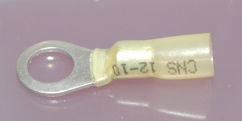
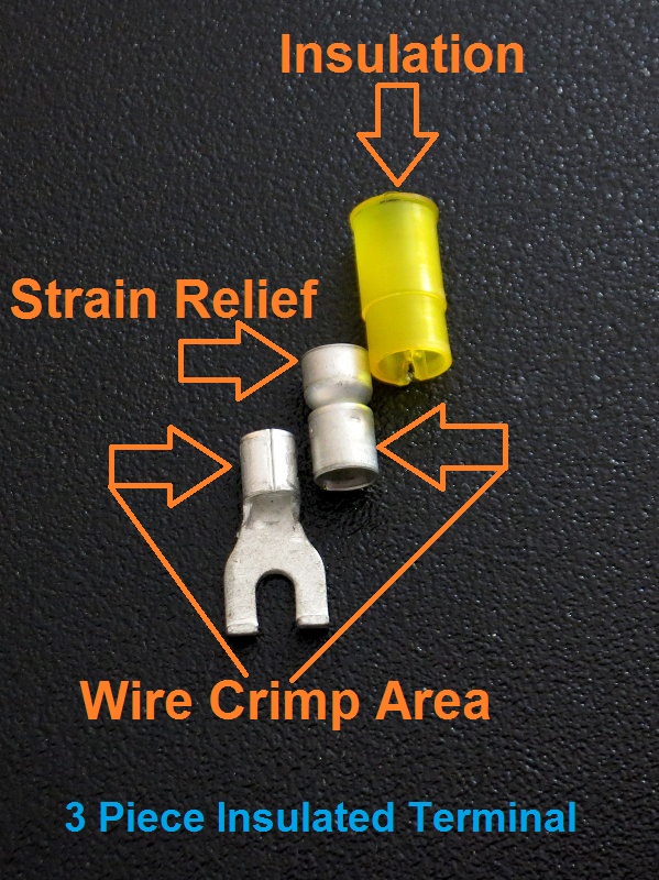
Anatomy of an Insulated Terminal
I took apart an insulated terminal to show why the crimper is referred to as double crimp tool. If your insulated crimp terminals do not have three parts, find some that do. AMP calls this type of terminal a PIDG but this one is made by Molex.
The wire crimp area gets one crimp and the strain relief barrel gets the second crimp. The dies of a double crimp tool are unequal in size. Using the appropriate crimp tool for an insulated terminal will create both the strain relief crimp and the wire crimp in one single motion.
If I were to disassemble a heat shrink connector all you'd see is the heat shrink and the terminal. You'd only have two pieces, not three, hence the term single crimp as it only crimps the crimp barrel because there is no strain relief barrel on a heat shrink terminal because the adhesive glue provides the strain relief..
Unfortunately, there are two separate tools because there are two different types of crimp connectors, insulated terminals and heat shrink terminals.
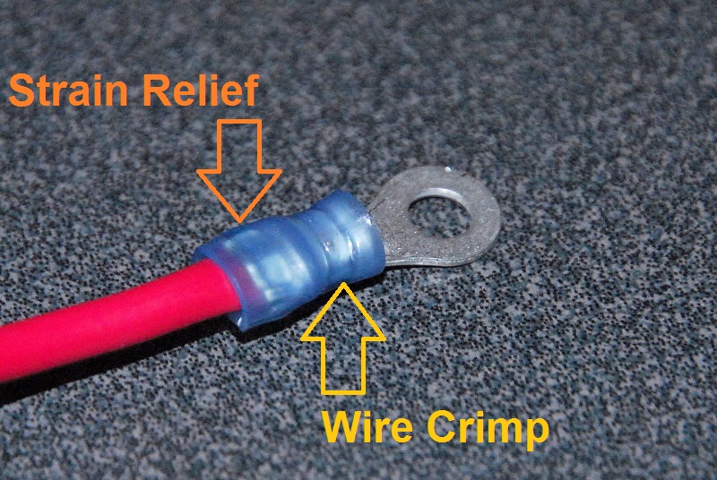
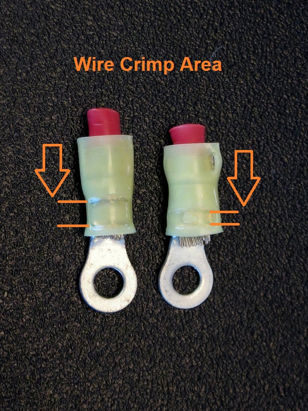
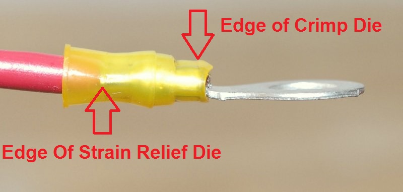
Double Crimps For Insulated Terminals
This picture shows where the two crimps are placed when using standard insulated three-piece crimp terminals. This is an AMP PIDG terminal.
A Mid-Quality "Double Crimp" Tool
This is an Anchor Products Double Crimp Ratchet Tool Part No. 701030. This crimp tool is not designed, nor intended for, use on heat shrink crimp connectors. This tool is designed to be used with the three-piece insulated crimp terminal like the one you just saw above.
Insulated three-piece connectors are often sold as "marine grade" from 22ga wire to 10ga wire. This tool allows for both the wire crimp and the strain relief sleeve to be crimped, in one motion at the same time, and will not release until the full crimp has been made.
One other key feature, of a decent quality ratchet type crimper, is that you can simply re-calibrate when and if they ever go out of adjustment.
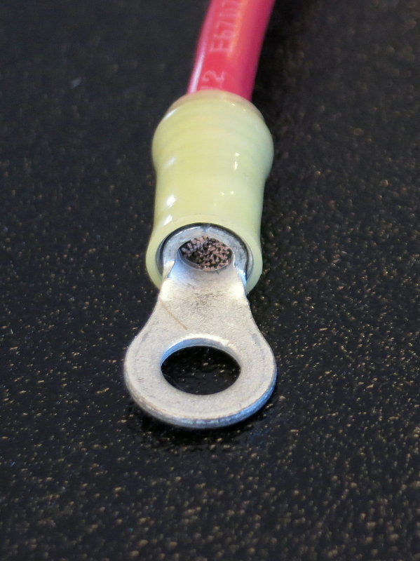
Insert Depth Incorrect
Before you can even begin to crimp the terminal to the wire the strip depth needs to be correct. Ideally the wire should protrude beyond the end of the crimp barrel by about 1mm +/-. This strip-depth is not correct because the wire does not stick out enough.
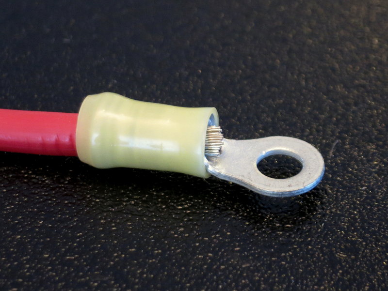
Insert Depth Correct
Here is a much better strip depth. This terminal is ready to be crimped to the wire.
*******CLICK BELOW FOR PAGE 4*******
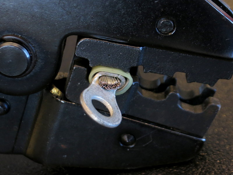
Horrible Terminal Crimp
Oh, oh this is not good...... With scissor-style crimp tools care needs to be taken to ensure the terminal is crimped as evenly as it can be. Often the seam in the terminal will be cocked slightly so that when the dies come down it winds up vertical.
What's Wrong?
#1 Terminal Not Inserted Correctly
#2 Strip Depth A Bit Too Long
#3 Brazed Terminal Seam Can Split
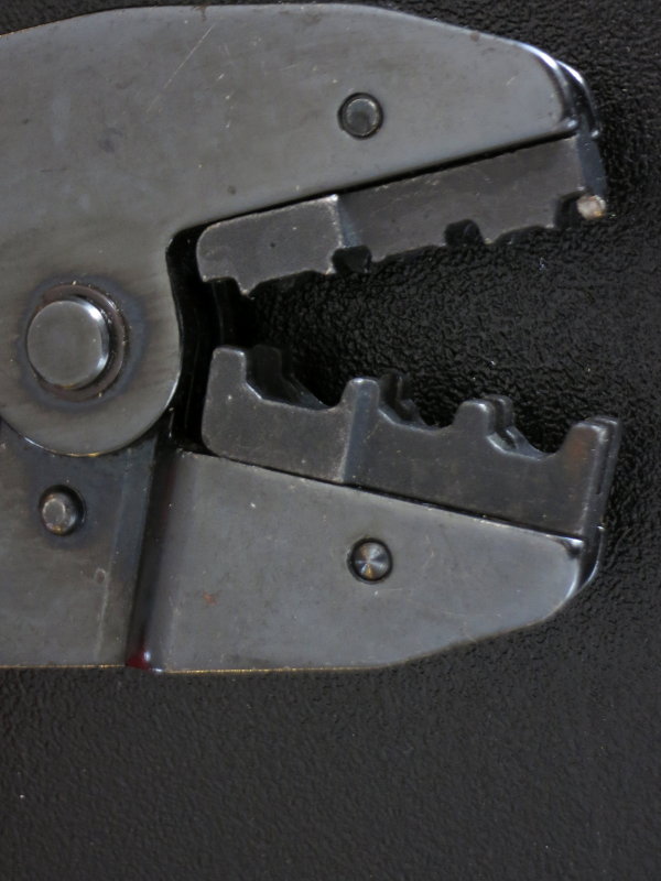
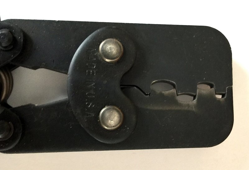
Scissor Style Crimp Tool
When I say "scissor style" crimp tool this is what I mean. The jaws close onto the terminal like scissors. While this type of crimp tool can work perfectly fine, they take more practice, care and attention to detail get repeatable crimp performance.
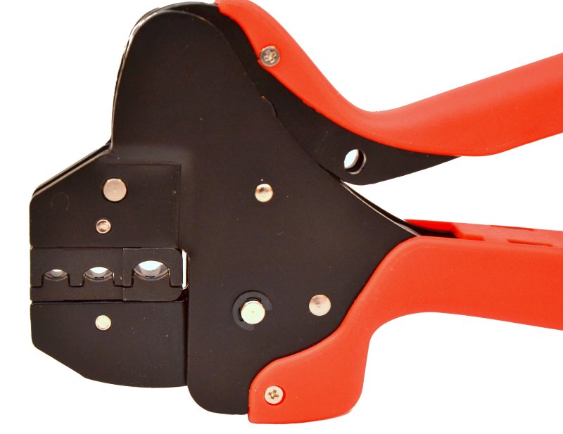
Parallel Action Crimp Tool
This is a parallel action tool or what I often call a guillotine-style tool. The dies come together vertically so all you need to do is insert the terminal, with the seam aligned vertically, and then squeeze. They make crimping repeatable, very, very easy and can have more exacting die tolerances. The down side is that parallel action crimp tools are a lot more expensive.
DO NOT USE !
If you crimp a terminal like this cut it off and start over. This is not a good crimp and could even be unsafe. The strain relief jaw even split the insulation open.
On of the reason I use AMP PIDG terminals almost exclusively, when using insulated terminals, is because the seam on these is brazed. Note how even with this horrible crimp the seam held together.
A lot of three piece terminals do not feature a brazed seam. This is one of the reasons why you will find AMP PIDG terminals on US Military fighter jets and attack helicopters but you won't find too many other brands of insulated terminals in the same application.
Strain Relief
Here is what the strain relief side looks like while being crimped with a parallel-action crimp tool.
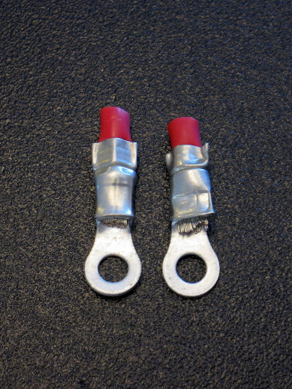
Good (L) & Bad (R)
On the left we have a terminal that was crimped using a parallel-action tool, and on the right the bad terminatio from above. The bad one was crimped with the scissor style tool.
An interesting observance to make is the wire crimp width of the crimp band area on the paralle-action tool, and how smooth the insulation transition is on the left vs. the right.
On the inexpensive mid grade scissor style tool the wire crimp die is considerably thinner and makes a much narrower crimp band on the terminal. This is why the parallel-action tool (left crimp) will repeatably wind up at about 190 pounds of tensile force (exceeds NASA and Mil-Spec), and the one on the right varies between 60 pounds and 105 pounds of tensile strength depending on how well you execute the termination.
Attention to detail matters.
Insulation Removed
With the insulation removed there are no surprises here either. The crimp on the right is still 100% unacceptable.
Strain Relief - Good (L) & Bad (R)
Here is a strain relief view of a good crimp vs. a bad one.
Double Crimp Jaw Positioning
One other important thing to consider is the orientation of the terminal in scissor-style tools. Here the terminal is aligned to give as even a crimp as is possible with this particular tool. While the seam may look fine the off center position of the terminal can cause it to "roll" to the center of the dies once you start to squeeze. This can create an uneven crimp. Center the terminal in the crimp nest and align it well before crimping.
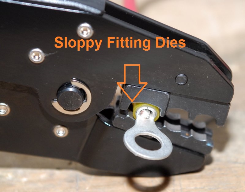
With mid-grade quality tools be aware that the dies can vary tremendously and some can be a pretty sloppy fit for the terminal, side to side in the crimp nest. Some of the low price point tools are actually not even made for AWG sized wire. A sloppy fit will allow the terminal to sit incorrectly in the jaws and can result in a bad crimp. Be aware of this in order to yield repeatable terminations.
A Tale of Five Off-Shore Crimp Tools
Unfortunately over the last 10 years or so cheap Chinese knock-offs of good quality American made tools have infiltrated this country. In this image I have five different ratcheting double crimp tools with five different die sets for insulated terminals. None of these tools perform the same nor do they make the same tensile strength terminations.
To the naked untrained eye they all look identical, but they are far from it.
Two of these "double crimp" tools have die sets are are NON-DIRECTIONAL meaning the strain relief side and the wire crimp side are identical. The strain relief and wire crimp sides of an insulated terminal are NEVER IDENTICAL SIZES.. This = FAIL!
The other three tools have dies sets that are nowhere even close to similar but they are all clearly marked Y, B & R. This = FAIL!
The Only tool here that really performs admirably is the Ancor tool. The die set in this tool is well machined and it makes a crimp that exceeds UL, ABYC & DIN standards.
Just like terminals, when buying crimp tools, stick to manufacturers that have a reputation to uphold.
Two of the pictured tools are from the same vendor using identical part numbers yet one has non-directional dies and the other has uni-directional dies. One thing Chinese knock-off artists are good at is consistency, yeah right... (wink) If you want to gamble buy a no-name Chinese crimp tool, if not stick with name brand tools from the likes of AMP, Molex, Ancor, T&B, Burndy etc.. Let these companies do the homework for you. With crimp tools you do tend to get what you pay for.
An Excellent Tool at a Great Price
This is the Compass Marine Pro-DCT:
After nearly three years of testing, 63 tools in total both domestic & imported, I finally developed an excellent quality controlled cycle (ratcheting), vertical-action double-crimp tool & double crimp die. The dies in this tool are as close to the AMP tools performance as could be sourced without jumping up $200.00 in price.
The machining and tolerances are excellent and this tool represents a tremendous value in a double-crimping tool. Yes, I make a small margin, for the Marine How To web site, to keep it FREE, and I pass the savings onto you the readers at a very competitive price. Every little bit helps keep MarineHowTo.com a FREE site.
Some US companies also import this crimp frame, with their logo & dies, & sell it for $265.00 - $440.00. I sell it readers of www.MarineHowTo.com for $59.70 (NOW ON SALE $48.00) and have done all the leg work to ensure you are getting a tool that actually makes a reliable crimp for yellow red and blue insulated terminals.
Please don't be fooled by mainland Chinese look-a-like knock offs, with horribly sloppy dies. They will not perform the same as this tool does. Yes, this tool is imported. At the value I desired, and what boaters are willing to pay, it has to be.
This tool is made in Taiwan not made in mainland China, like the cheaper poor crimping tools are. You'll not find a better double crimping tool for the money and certainly won't find a quality vertical-action tool at this price or quality point, I know I bought & tested 63 of them.
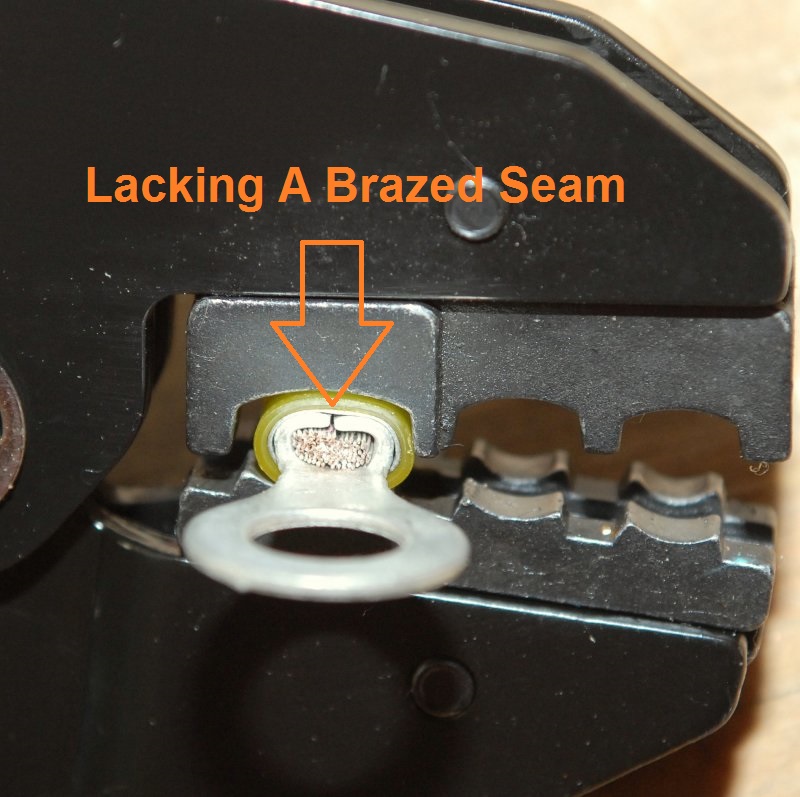
Terminal Quality - No Brazed Seam
This photo shows a fairly even, but not perfect, crimp taking place.
What we are really looking at here is a run-of-the-mill quality three piece terminal. While it is a three-piece terminal, this one does not feature a brazed seam and we can see that even with a fairly even crimp the seam is beginning to open. Brazed seam insulated terminals, like the AMP PIDG terminals, cost more but are a better quality terminals.
The Crimp
While this crimp was executed on an okay fashion, by the Ancor tool, it still lacks a brazed seam and will not yield comparable tensile strength numbers to a brazed seam terminal.
This crimp tool makes an "okay" crimp but not one that is equal to something that would be allowed in the aerospace market. Pair the Ancor with a brazed seam terminal and it can pass UL & even Mil-Spec on some sizes..
Profile View
Here you can see the "double" part of the double crimp. Both the barrel and the strain relief have been crimped thus the term "double crimper".
One area to be aware of is the spacing between the wire crimp die and the strain relief die and the terminals you are using. Here the spacing is a bit wide.
Once you choose a double crimp tool experiment with different brands of three piece terminals to find the best match. Once you have a good match stick with that terminal and that tool.
Checking The Strength
In the sailing & boating community I often find lots of skepticism surrounding crimped terminals. This of course is of little surprise to me, because the average crimp tool I see on boats I set foot on costs somewhere in the neighborhood of $4.50. I suppose I'd be a skeptic too especially if I'd spent less than the cost of a Whopper Jr. for my crimping tool. (grin)
After thinking about all the skepticism, I decided to do a little illustrative experiment to display the strength of a crimp executed with mid-grade crimp tool.
To do this I used the heat shrink crimp termination you just saw being made in the heat shrink terminal part of this article. The wire used here is 12 AWG UL 1426 tinned marine grade wire and the rather affordable FTZ crimp tool made the crimp.
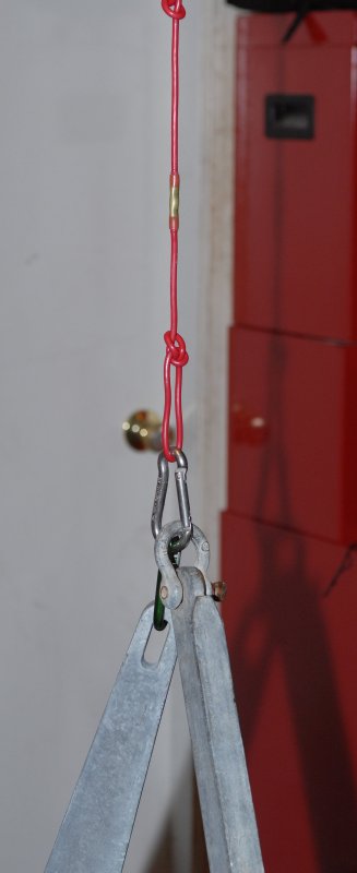
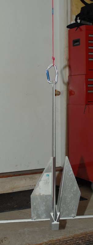
This photo shows the crimped butt connector holding the entire weight of two 35 pound class anchors. The static load hanging on this butt splice is approx 70 lbs..
Pretty Strong!
This picture sums it up pretty well. A well executed crimp termination is much stronger than most ever assume.
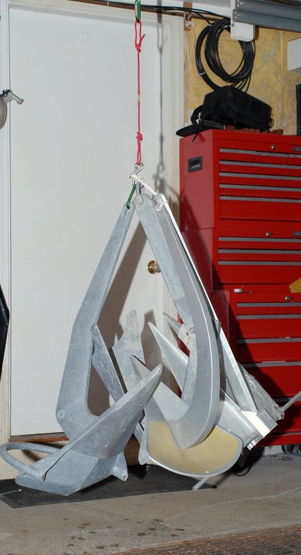
Clearly I got bored with the excitement level of just two anchors and decided to up the ante & try it with four anchors. Shown here is a Rocna 33 (33 pounds), Spade A-80 (16lbs.), Super Max 35 (35 pounds) and a Fortress FX-16 (10 Lbs.).
Yes, you read it correctly, that 12GA wire and crimped heat shrink connector are supporting approx to 95lbs.
As shown this crimped butt splice, made with a $50.00 mid-grade tool, is exceeding ABYC, UL and DIN crimp standards.
FOR THE FULL CRIMP TOOL SHOOT OUT VISIT MY FORUM AND SEE THE VIDEOS AT THE LINK BELOW:
OK I wanted to test the strength of the adhesive lined heat shrink to decipher it's added benefit in overall total joint strength.
To do this I striped the wire as I would normally do then instead of crimping the butt connector I simply applied heat and melted the adhesive lined heat shrink around the wires jacket.
This photo shows the actual connection that I used in the photo below.
The Results !
I was quite impressed by the durability of just the adhesive lined heat shrink tubing.
The heat shrink alone actually held my 10lb Fortress FX-16 anchor just fine. I then tried my 16 lb. Spade A-80 anchor and the connection failed before I could even turn around and get my camera! Still ten pounds is not bad and it should certainly keep any moisture out. Interestingly enough a yellow terminal crimped with the "el-cheapo" crimpers from the first picture held less than ten pounds in my load testing. Based on that the adhesive is stronger than a cheapo pair of crimpers.... Ouch!!
So the failure point is somewhere between 10 and 16 lbs. static load, for just the heat shrink alone.
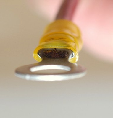
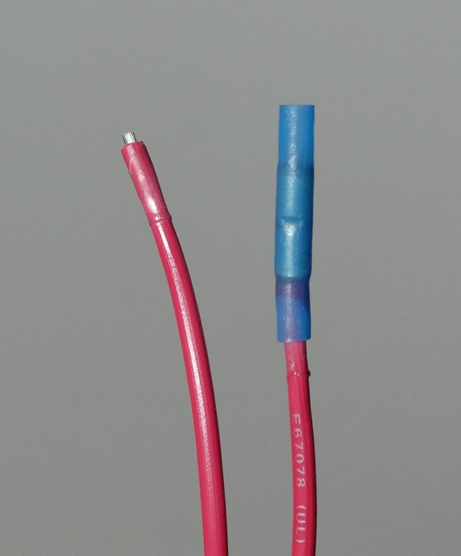
What Happened?
As you can see in this picture the jacket stretched, got thinner due to elongation, and pulled away from the adhesive. I had stripped that wire just like I would have had I been crimping it. Before the failure there was considerably more wire showing. If you look closely you can see the remaining adhesive beginning to fail on the end that had not yet come apart.
A Tale of Two Crimps
OK I did one last experiment. This time I made a crimp with my Klein crimper/strippers and one with the CMI Single Crimp Ratcheting Crimper. I then cut the crimped terminals open with my Dremel tool and took a peak.
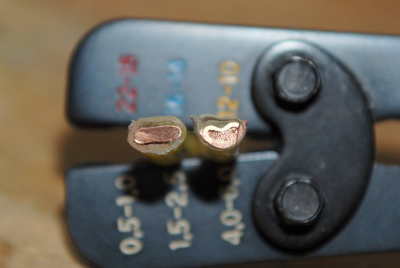
The crimp on the left was made with the CMI Single Crimp Ratcheting crimper, which is a mid quality crimp tool, and the crimp on the right was made with my Klein dimple crimper, a very mediocre crimper, but also the type many boat owners use to make crimped connections.
I now understand why many boaters think "air" can get into a crimp and corrode it. If you look at he crimp on the right, made with the dimple crimper, you can still see strands of copper wire. The crimp on the left is far superior and has in fact cold worked or cold formed, into a near solid mass. While it is technically not a solid mass of copper there is almost no room for moisture or air to get in between the strands of wire and begin wicking. I think the photo speaks for its self and shows why a well built crimping too is worth the money..
Crimp vs. Solder
This discussion has been beat around the net more than a tennis ball. I think the best statement on soldering a crimped terminal comes from the Senior Product Engineer Tom Michielutti at AMP. AMP is one of the most widely respected suppliers of crimp terminations to the US Aerospace and military sectors. Below is the statement from the senior engineer at AMP. NOT MY WORDS.
Begin Quote:
"Subject: Soldering Crimped Connections & Solder in Crimps
This subject is discussed in AMP�s internal �Fundamentals of Connector Design� course.
Soldering Crimped Connections
In the minds of some customers, fortunately a diminishing minority, the reliability of crimped connections can be improved by soldering. In fact, soldering can degrade the performance of properly crimped connections. Such degradation can arise from the effects of soldering temperatures, the potential corrosion from improper cleaning of soldering fluxes and the effects of solder wicking on the conductors. Solder wicking causes the multi-strand conductors, which have high flexibility and stability against vibration, to become, effectively, solid which degrades both the performance characteristics mentioned. For these reasons, soldering of crimped connections is not recommended.
Should Solder be Used in Crimps?
Crimps are designed to work without solder or solder-dipped wires. Solder present in a crimp changes the deformation, metal flow, cleaning, welding, and residual force characteristics designed into the crimp. Soldering would be an additional heat producing assembly step. Test results show that soldering or solder-dipping wires before crimping does not produce a termination superior to that obtained in a properly applied crimped termination. Some tests specifically show detrimental effects due to soldering or solder-dipping (e.g. soldered crimp terminations can lose some ability to withstand vibrations and flexing, due to solder embrittlement of the copper wire, and/or due to solder wicking up the strand of stranded wire to form a short length of solid conductor near the
termination). The terminated conductor then does not have the flexure strength characteristic of strand wire, and should behave more like solid wire which fails quickly in flexure testing."
The above is a direct quote from AMP.
PHOTO: The cut open pictured crimp was made with the tool on the left in the bottom photo. An AMP yellow PIDG terminal and an AMP crimp tool. This combination is certified for aerospace use. When crimped with a 12 AWG wire it will also withstand at least 190 pounds of pull out force and do so repeatably within a pound or two every single time. This is 80 pounds beyond Mil Spec!!
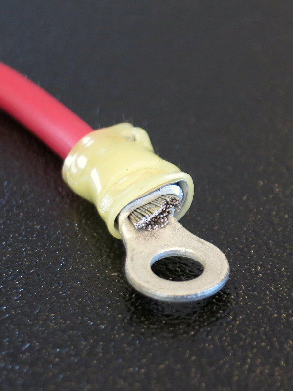
If You Still Insist On Soldering
Here is an example of what I consider a Mickey Mouse version of soldering but I see it. In this case I crimped first then soldered the exposed wire to the crimp barrel. If you get good at soldering this is not difficult but it does take practice to do on a boat and it does require a quality soldering iron.
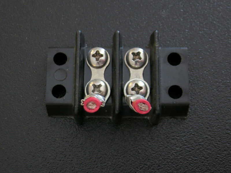
It should be noted that the NASA, Military and Aerospace wiring standards specifically prohibit crimping terminals to solid conductor wire or to solder-tinned wire.
This is NASA's take on soldering solder-tinned wire:
"NASA 4.3.4 Crimping - Stranded wire shall be used for crimping (Requirement). Crimping of solid wire is prohibited. Crimping of solder tinned wire is prohibited."
"Solder tinned" wire is different than tinned STRANDING where each individual strand is tinned. Solder tinned means you pre-tinned the end of the wire before you made a crimp. DO NOT DO THIS.
If you insist on soldering the the quasi optimal way to do this (really there is no optimal way because you don't need to solder crimped terminals) is to crimp first then solder.
As can be seen with the right tools and technique you can solder the end of the terminal and not melt the insulator or wire. You won't achieve this with a $5.00 Radio Shack soldering iron.
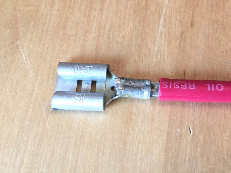
If You Really Must Solder
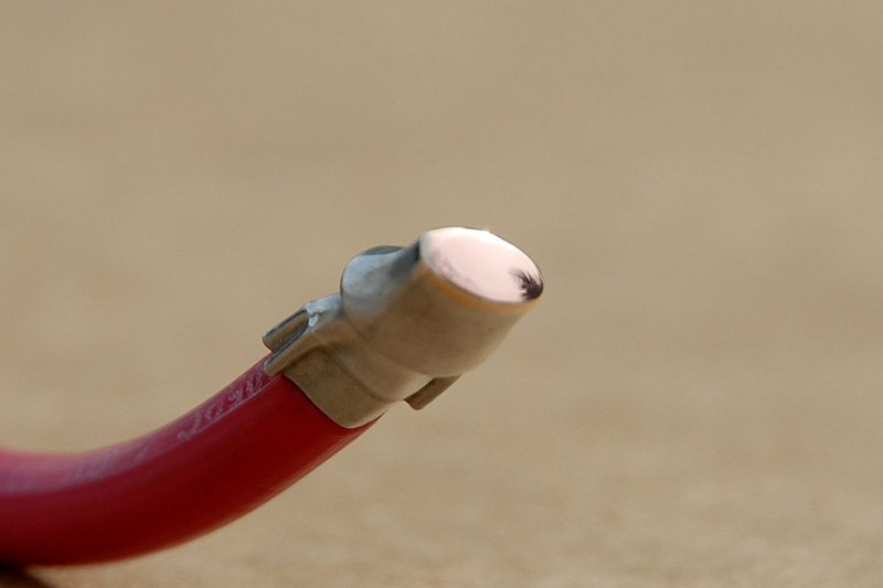
This type of terminal barrel lends much better to crimp then solder than do insulated terminals. This is a bare non-insulated "B" or "F" type crimp terminal. You crimp it with the correct tooling then apply solder to the very end of the wire and let some flow into the "B" for butt cheek.
NOTE: Please take note that in this image, and in the last image you saw, proper crimping has not allowed solder to flow beyond the crimp-band. Solder that flows beyond the crimp band would create the proverbial "hard spot" which ABYC and other standards want to avoid.
If you use the proper tools, the solder should not flow beyond the crimp-band to the part of the wire that needs to remain flexible. If you use Dollar Store grade tools well, sure, you can create a hard spot and the wire could fracture.
This type of crimp takes yet more tools in your bag, terminals that are harder to find in a good quality level, you will need to self-insulate the terminal and it takes considerable time to execute properly.
IMPORTANT: I do not recommend nor suggest doing a crimp & solder as it is really unnecessary IF you use the right tools to begin with.
Terminal Cut Open
Here I have used my side cutters to nip away at the crimped then soldered AMP PIDG insulated terminal. As can be seen the solder did NOT wick past the crimp-band area and create a hard spot. This is because I made the crimp with proper tooling to begin with thus making soldering unnecessary. If you used a crappy tool, yes you would create a hard spot and yes the solder can wick beyond the crimp-band area.
IMPORTANT: These images are for illustrative purposes only and are not a suggestion nor recommendation to crimp and use solder. As they say; your boat, your choice.
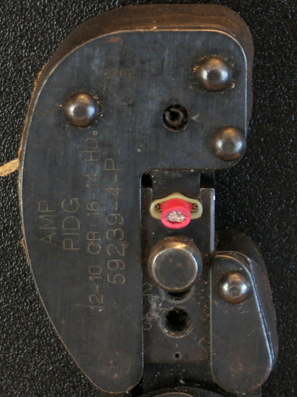
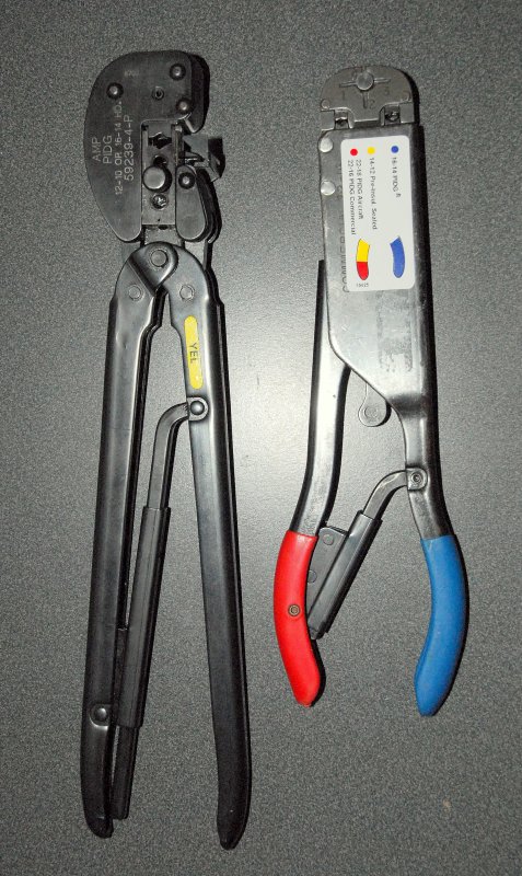
Which Crimpers Do I Use For Insulated Terminals?
I actually don't use many of the crimpers shown in the body of this article, not that they are not okay tools, but as a professional I prefer the crimps made with professional level tools like shown here..
If I am putting my name on a crimp only professional grade tools such as these AMP crimpers will make me happy. Please do not feel you need to run out and buy these, as everyone has their level of quality that will make them happy, mine is obscenely high.
These parallel-action crimp tools are used in the aerospace industry to make certified aerospace quality crimp terminations. They can be re-built and re-calibrated by certified re-builders / re-calibrators and will literally last a lifetime. Each of these tools has made thousands and thousands of crimps and they remain in-spec.
The one on the right crimps blue and red insulated spade and ring terminals and the one on the left crimps yellow insulated spade & ring terminals only.
The gold standard AMP T-Head crimper on the right is part# 59250 and sells new for $1347.00. The one on the left is part # 59239-4 and sells for $671.00. They can often be found used through a re-builder or re-calibration specialist for considerably less money.
Before you can begin to complain about how expensive a DIY/mid grade crimp tool is just think about what the ones I use cost.. (wink)
What About Heat Shrink Crimps?
While I love heat shrink crimp connectors I was never fully satisfied with the available crimp tools for professional everyday use. I first developed some custom tools by modifying existing crimp tool frames, testing the pull strength and then worked closely with a German first then a USA manufacturer, who builds crimp tools for AMP, to land on this tool.
The Pro-HST crimper is what I consider a pro-level tool for heat shrink crimp terminals. While this tool is not inexpensive it is made right here in the USA in small lot quantities. The pricing certainly reflects that it is US made and made in small quantities. I generally sell this tool to professionals and occasionally a very discriminating DIY.
The Crimp Dies Do Not Just Squash The Terminal
Cheaper tools essentially squash the terminal into an oval shape. With the Pro-HST the terminal fists with less space between the crimp nest-walls of the crimp die. The jaws then come down and compress the terminals so it has a more 360 degree compression of the terminal rather than just a squish action. In testing the Pro-HST beats all my others in terms of pull out strength for heat shrink terminals, including comparisons against high end German tools that cost 4X as much.
MAY-2006
Help Support This Site
Like what you saw or read in this article? Was it helpful? Could the information save you some money? Would you like to see more articles like this?
If so feel free to donate, support the site, and keep it growing. Please DO NOT feel obligated at all. If you like it and want to make a donation, please do. Your donations help keep the content coming and also help keep it FREE.
Click the DONATE button below if you would like to make a donation via PayPal.