1-1-16
Engine Panel With Ammeter = Dangerous
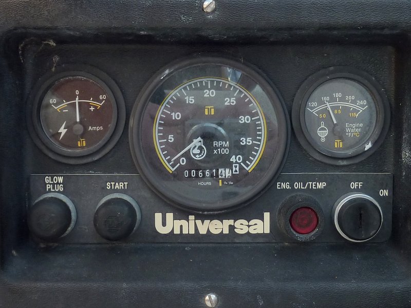
If your Universal engine panel looks like this, and has an ammeter, you are due for some wiring fixes.
The factory wiring, with an ammeter in the panel, is flat out dangerous and this really needs to be addressed if it has not yet. It amazes me how many boats are out there still using this unsafe set up.
If you have an ammeter in your panel REMOVE it and jump your alternator 6" over to the starter post with heavy wire. Another alternative is to run your alternator direct to the house bank with a fuse or breaker within 7" of the battery and then add a combining relay or Echo Charger.
I have also measured voltage drops of 1.2+ volts or more at just 10A of charge current through these circuits. That means your alt is putting out 14.2V+ and the battery is seeing just 13.0 volts and is being chronically under charged.
1-1-16
Early Universal Engine Charging Circuit
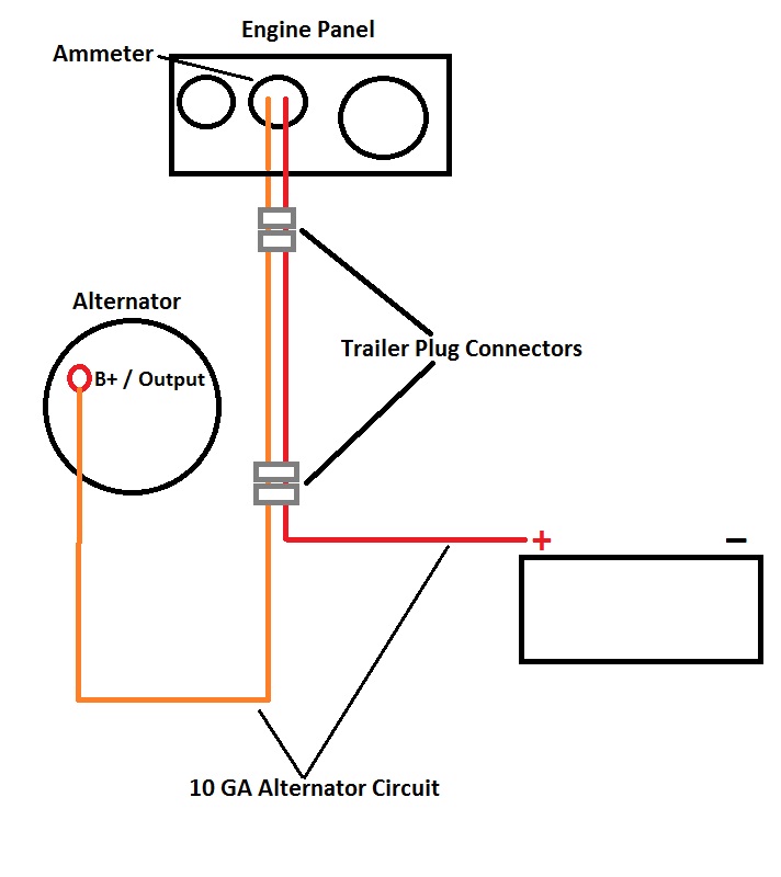
Here's a very crude diagram that shows the alternator charging circuit most often found on these early Universal engines. Universal/Westerbeke Corp later changed this dangerous set up, removed the ammeter and jumped the alternator directly to the starter lug. Interestingly enough most of the Westerbeke engines never used a factory installed ammeter and it was sold as an option.
The factory charging circuit leaves the alternator with an orange 10GA wire then most often travels through TWO trailer type connectors to an ammeter at the engine panel. This high amperage current then has to travel all the way back to the battery switch (please not I did not draw the battery switch on this diagram), through more undersized wire, where it finally picks up some larger gauge wire before finally heading to the battery to charge it. These factory circuits often had a 30A fuse in them which was undersized even for some of the alternators shipped on these engines. Owner often put higher amp fuses in or bypassed them all together.
The existing alternator charging circuit, with ammeter, runs as far as 25+ feet on some boats before it gets to the battery banks. On most of these panels the entire current of the alternator runs through 10GA wire and a ridiculous trailer type connector that is a huge point of resistance as these boats age. I have pulled many of these connectors and wires out that were literally melted.
With house power demands getting larger and larger and battery banks getting bigger and bigger, and accepting significantly more charging current, these circuits have been known to literally melt down and in some cases catch fire and this is all with stock alternators. I have seen DIY upgrades to 100+A alternators still utilizing this circuit. PLEASE DO NOT DO THIS!!!
1-1-16
Bypass The Orange/Red Circuit
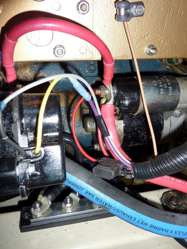
Here's the quick and dirty fix. Try to focus on the red wire between the back of the alternator and the starter post. Simply jump the alternator output to the starter post and disconnect the orange wire. With this jumper the alternator output bypasses the 20+/- feet of teeny tiny 10GA wire and uses the large gauge starter wire to make its way back to the battery switch and then to the battery banks. Minimal voltage drop compared to the 10GA circuit and much less resistance and heat without going through all that small wire and two trailer connectors.
Please note that I generally advise running the alternator output directly to the house bank, not to the starter as shown here. You can then install an automatic combining relay (ACR) or an Echo Charger between the banks to charge both simultaneously. Doing this will remove the potential for fried diodes via the flipping of the battery switch through the OFF position. While not 100% necessary it is a good upgrade,and , as I always say, "while you're in there" might as well.
Even if you choose not to run the alternator direct to the house bank you are far safer with the new jumper than you were before.
1-1-16
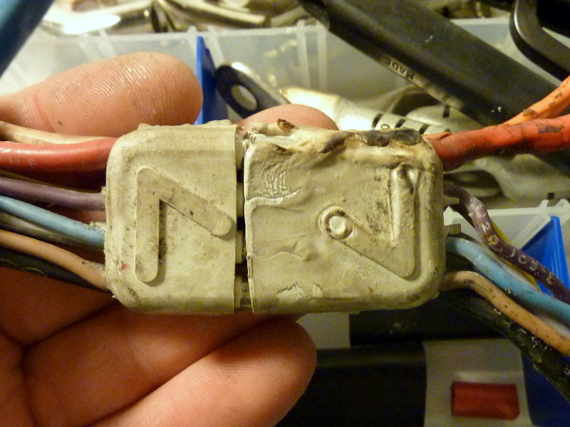
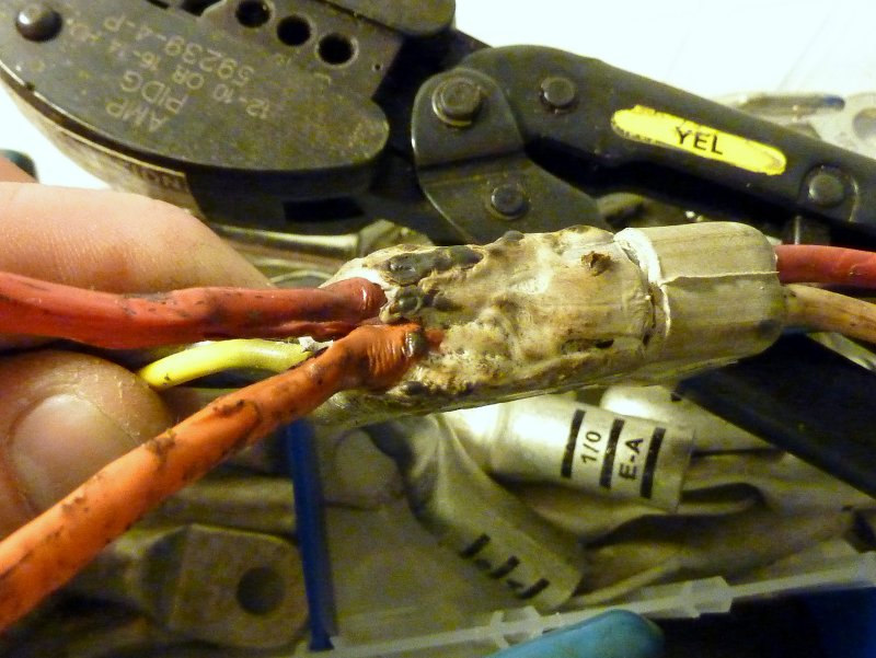
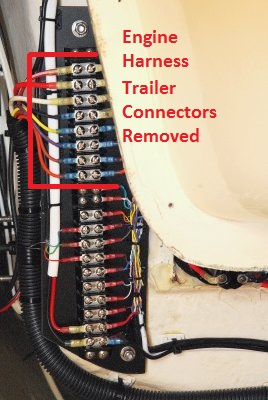
The Infamous "Trailer Connector"
So this is what you are looking for, the trailer connector. Once you find them, there are most often two in there, CUT THEM OUT!!! Replace them with a buss bar and ring terminals or butt splices. These connectors can start fires! They are not designed to have 50+ amps running through them let alone the alt upgrades to 75+ amps I have seen still running though this grossly under designed circuit. This one is clearly melted as you see in the next few photos.
On one boat the engine had been upgraded to the optional 72A alternator and was still running through this circuit. Ouch!! For charging batteries you want minimal voltage drop between the alternator output and the battery bank. For example a stock alternator with a 14.2V set point at 3% voltage drop would have the battery bank seeing about 13.8V. This type of volt drop can chronically undercharge your bank and can lead to premature sulfation and early battery bank death.
This particular boat had 22' of orange and red 10GA wire before it hit the battery switch. Even if we figure the 72A alt will never put out 72A, unless cold, and we base our calculation on just a 60A output, at a 3% volt drop this would require 4GA wire, NOT 10GA. If you want a 2% voltage drop you'd need 2GA wire and this is a far cry from 22' of 10GA wire.....
1-1-16
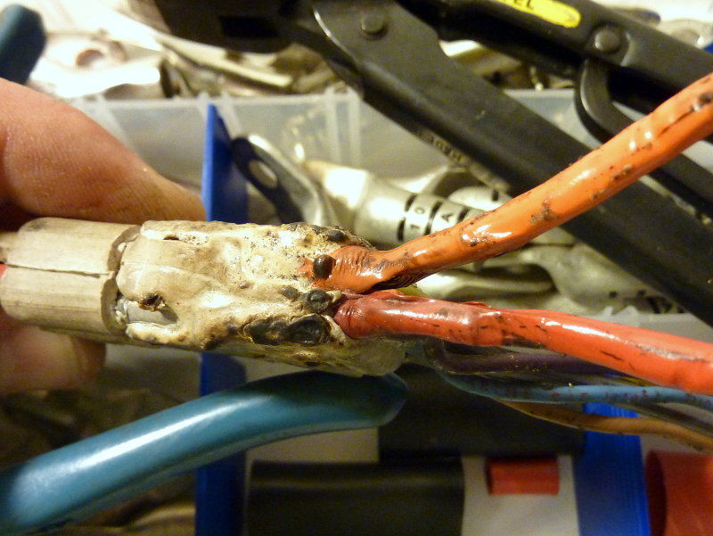
Melt Down!!
This came off a mid 80's production boat with a 5416 Universal. The owner had no idea what had been lurking below under all that electrical tape.
I can not stress enough how important it is to bypass the factory charging circuit and REMOVE the trailer connectors.
1-1-16
Towering Inferno!!
I remember that move from the 70's and would hate for that to become your boat. Let this image sink in!!!!!
1-1-16
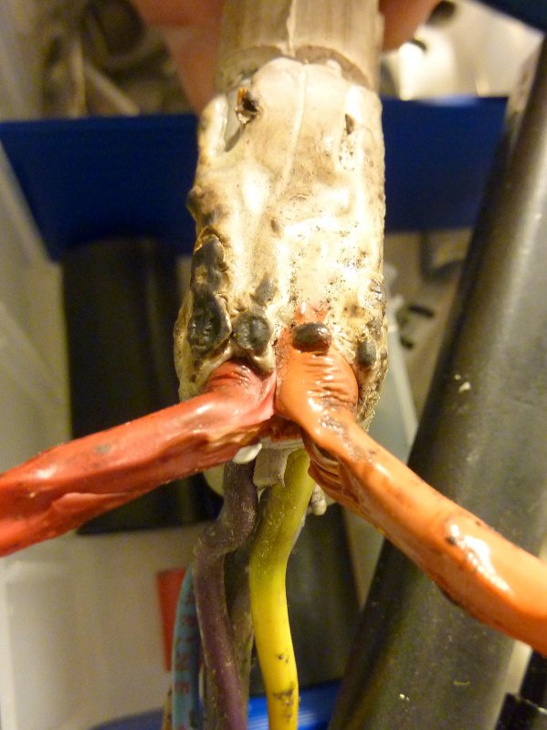
Fused Together!!
As you can see these two wires were pretty melted together with jacket blistering and all. A few more deep discharges of this battery bank and this could have been a full blown "burned to the water" situation. This wiring fix for early Universal engines is NOT something to take lightly..
1-1-16
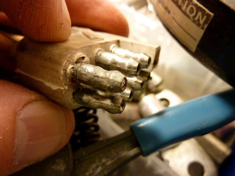
Just a Little Oxidation
Just a little oxidation is all it takes with these cheap connectors to cause resistance in a high amperage circuit. The two pins closest to you are the orange and red wire pins for the charging circuit. Note how clean the low current pins are in the back ground. As I mentioned these connectors are not safe to run this much amperage through.
02-APR-2016
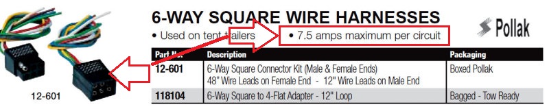
Circuit Amperage Rating
Out of curiosity I contacted three different manufacturers of this type of plug/pin configuration, Hopkins, Pollak and Peterson and the maximum continuous rating for this type of pin appears to be about 7.5A. One company told me 7.5A continuous and 15A for short duration's like brake lights but the bottom line is that this very popular male female pin/socket, the same exact type Universal / Westerbeke used to pass 50A + of current is really only rated for 7.5A and perhaps 15A for very short dirations. Are we beginning to see how bad this problem really is?
Universal apparently decided on their own that it was safe to push 50A plus of alternator current through these small pins. Wow!!
1-1-16
So How Do I Remove Them?
On this particular boat I simply used heat shrink ring terminals and a Blue Sea Buss bar. This connector did not have any high current running through it, as this was on a later Westerbeke, but I still remove the problematic and quirky trailer connectors as I find they are very poorly suited for the marine environment. Even without any high current circuits they still cause issues.
These heat shrink rings create a significantly more reliable and better connection. Once coated with BoeShield, No-Ox-Id Special A, or similar, corrosion protection & electrical gremlins are virtually a non-issue.
1-1-16
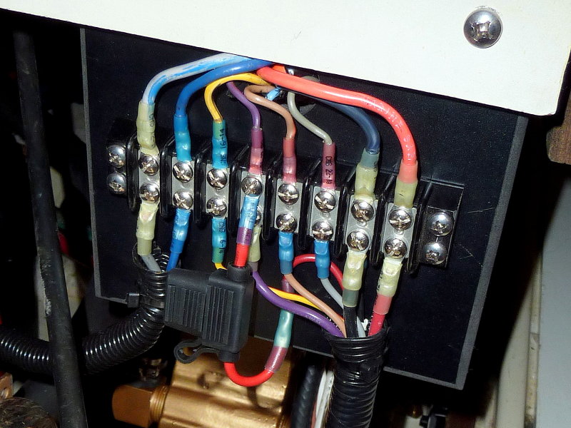
Another Trailer Connector Removed
Here's another example of a trailer connector removed and replaced with a Blue Sea terminal strip, ring terminals and adhesive lined heat shrink terminals.
1-1-16
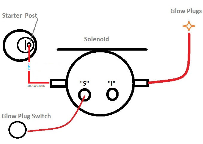
What About The Glow Plugs?
The other high amp circuit on these earlier engines is the glow plug (GP) circuit. While the two cylinder engines can do ok with a 10GA GP circuit, the three and four cylinder engines can suffer from "slow glow" and burned out ignition switches.
A quick and easy way to fix this is to insert a simple solenoid or "pre-heat solenoid" into the glow plug circuit. To install this solenoid you simply steal power via a 10GA or larger wire from the starter post. Please be sure to fuse this run as close to the starter post as possible or within 7".
You then snip the glow plug wire, add ring terminals, and place the glow plug end on the opposite side of the solenoid from the starter wire and the glow plug switch end now goes to the "S" terminal on the solenoid.
Now when you hit the glow plug button a the solenoid (heavy duty switch) closes and creates a direct path between the high current, large gauge, starter motor feed wire and the glow plugs. All the glow plug switch has to do now is energize the solenoids coil, and this takes very little current. You are no longer running high amperage's through 20+ feet of 10GA wire, suspect terminations and switches that are only rated for minimal amperage.
Most all newer Universal, Westerbeke, Beta, Yanmar etc. engines, that utilize glow plugs, have a solenoid in the pre-heat circuit. You can buy one from MarineHowTo.com, called the "Start Assist Relay" and save money.
NOTE: When you do this upgrade we suggest cutting your glow button plug push time to 7-15 seconds maximum. If you hold for the duration that you used to, with the old and dangerous wiring harness, you can literally cook your glow plugs and burn them out.
Glow plugs draw more than most folks assume they do. The typical glow plug off a Westerbeke engine will draw about 22A when cold and as they head up the amperage drops as low as about 11A (test done using constant voltage source and measuring GP current). On a three or four cylinder engine you multiply this load times three or four. Some glow plugs may draw less but most will draw 10A+ each. When you consider that most engines only ship with an ignitions switch capable of 10A or 15A you can see why a glow assist relay can really help.