09-MAR-04
Removing The Coupling From The Transmission
Day One:
1) Loosen the packing gland nut.
2) Loosen and remove the four nuts between the transmission and coupling.
3) Push the shaft towards the stern separating it from the transmission.
4) Apply penetrating oil to the shaft and coupling with PB Blaster or Thrust. Do not use WD40 or Liquid Wrench these are NOT true penetrating oils. PB Blaster or a product called Thrust are incredible products. Apply to both the prop end of the coupling and the transmission end by sliding the shaft towards the stern tube.
5) Next align the shaft upright and remove the seizing wire and two bolts that lock the coupling to the shaft. Next fill the two bolt holes with PB Blaster, wait a few minutes for it to absorb into the holes and repeat a few times. By hitting both ends of the coupling, and the center where the holes are, with PB Blaster, you will get better Penetration than just wetting the prop end of the coupling. It's best to fill the cap with PB Blaster & then use a Q-tip or use an eye dropper for application.
09-MAR-04
Removing The Coupling From The Shaft
Day Two:
*WARNING: Unless your shaft is very new, like this one was at just a few months old, be VERY, VERY careful using this method.
I hate to even suggest or share this method but it "can" work. There are shaft couplings that can be removed this way, if you are very careful.
Please be aware that it is VERY, VERY easy to bend a gear box output flange, making future alignments near impossible, or actually break one see photo after this one. A better method is to have a plate made at a machine shop with the same bolt pattern as your coupling and use it to press the coupling off and NOT use the transmission flange.
Buck Algonquin also makes a flange puller that works BUT you need good clearance between shaft coupling and gear flange.
If using this press off method it will be IMPERATIVE that you take both the coupling and the shaft to a machine shop and have it tested for run out and then perform a "fit & face" before re-installation.
It takes VERY, VERY little force on these couplings to throw them out of true. Throw it out of true and you'll cause shaft whip and will have a boat that is physically impossible to align. Do not cut this corner and do not over tighten the "press bolts".
This coupling came off easy compared to many. Still when I took it to the machine shop it was out by 7 thousandths. Lucky the gear box flange still spun true. I suspect this shaft came from the factory with an improper "facing" as appeared to entirely lack any evidence of ever being "faced". This would have made for an impossible alignment.
The Process:
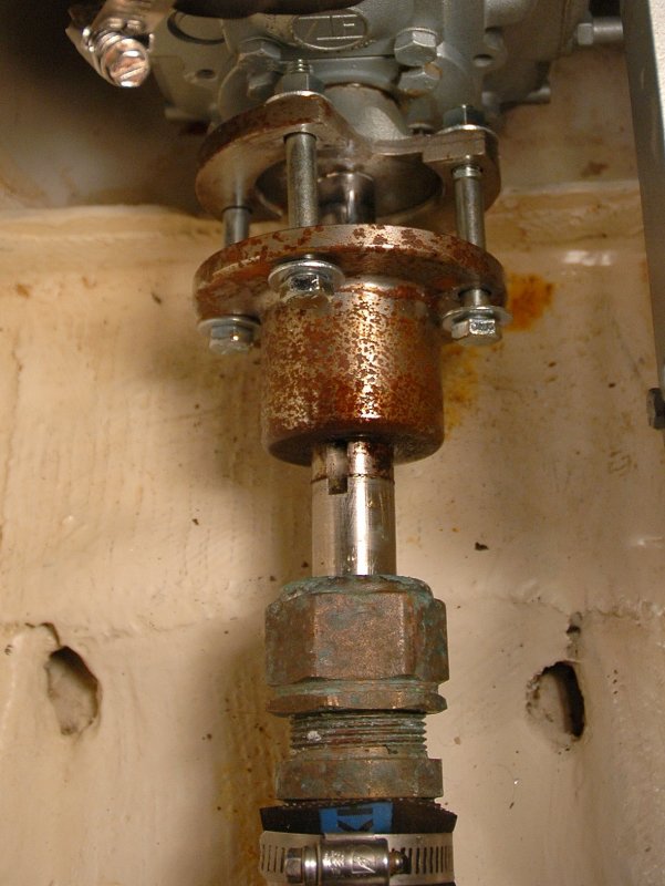
1) Insert a deep drive socket that is slightly smaller than the shaft size between the center of the shaft and center of the transmission hub. See the picture below for a close up of the socket between the coupling and the transmission hub.
2) Insert four long threaded bolts, preferably without shoulders (the part on longer bolts with no threads). This boat was only two months old and the coupling was not that tough to get off but it had already begin to rust on. Luckily the layer of rust was not enough to disturb the "fit". Other boats where I know they are rusted on I would use fine threaded bolts and a custom made "pressing plate" NOT the gear box flange.. Be sure to use washers between the coupling and transmission hub and begin tightening EVENLY.
3) After some initial tightening, and with the bolt pressure still on the shaft and coupling, you may need to go outside the boat and tap the prop shaft towards the bow, yes the bow, with a wood or lead mallet. Remember this is NOT a driving blow more of a "tap". This is not a pounding with the mallet, just a light strike. If you hit it hard you can brinell/dimple the bearings and or races in the gear box and ruin them. Then when back inside a heat gun can be used to warm and expand the coupling. Do not use a torch with the PB Blaster. A heat gun will work wonders. Heat and rotate, heat and rotate.
Use a scrap piece of maple between the mallet and the shaft to prevent potential damage to the end of the shaft from the hammer if you don't have a soft metal or wood mallet. Then re-enter the boat and continue tightening until the coupling is off the shaft. Apply heat to the coupling while it is under slight pressure will help expand it and hopefully aid in getting it off. Please DO NOT over-tighten the bolts! If it does not want to come off please STOP and DO NOT damage your gear box trying. Remember it takes very little force to throw these flanges out of true.
4) Optional: After the machine shop visit bring the coupling home to clean and paint it with a rust proof paint.
*WARNING * WARNING * WARNING: Be very careful NOT to get PB Blaster near ANY engine or transmission seals. True penetrating oils will EAT engine seals causing catastrophic failure of that seal. The most common seal DIYers destroy is the transmission output shaft seal. Be very, very careful using PB Blaster on your engines coupling bolts and DO NOT use the spray feature when working that close to seals. If you need to use a penetrating oil on coupling bolts fill the PB Blaster cap with the penetrating oil and then use a Q-Tip to dab PB Blaster on the bolts being very careful not to drip ANY on or near the transmission output shaft seal.
09-MAR-04
The Coupling Has Started To Move
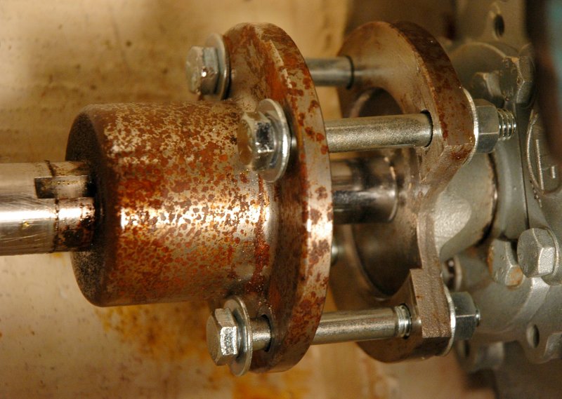
In this picture you can see the effect, and penetration, of the PB Blaster penetrating oil. The coupling has broken free and is beginning to come off through the tightening of the bolts.
If you have trouble getting the shaft and coupling apart you can heat the center of the coupling very slightly with a heat gun (make sure you have an extinguisher on hand just in case) heating it in the CENTER will draw the PB Blaster into the coupling due to capillary heat draw.
09-MAR-04
A Reinstalled Coupling
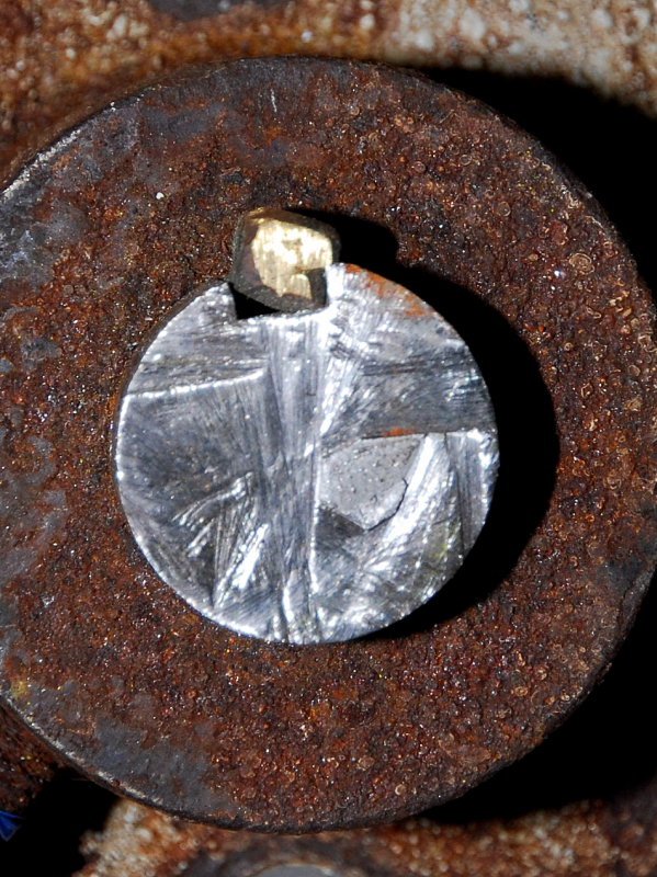
Here's what can happen when the fit of the coupling is too sloppy from a removal and re-installation.
Remember a straight coupling to the shaft is a light interference fit. Removing a rusted coupling, and breaking that rust layer free, can destroy this very, very narrow window of "fit".
Click this image and look at the key. It should NOT look like this. This is caused by a poor fit!
09-MAR-04
DO NOT OVER TIGHTEN
Please DO NOT over tighten the draw bolts. This boater was very lucky he broke the shaft flange and not the gear box flange. Despite his gear box flange not breaking, it is now severely OUT OF TRUE. The only way to fix this is with a rebuild.
Despite it not breaking it still cost $1750.00 to fix the BENT gear box output flange which required a re-build of the gear box. Remember these flanges are going to be aligned to 0.003" when you put her back together. It does NOT take a lot of force to bent the output flange by 0.003".
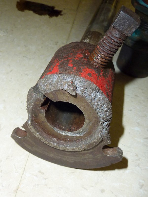
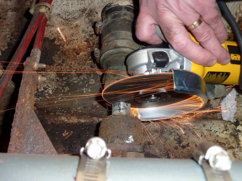
If the coupling won't come off you can cut the coupling just over the key way as seen in this photo. Creating the cut at the key way will ensure that you don't damage the shaft. One cut it will relieve the pressure and the coupling will then come off.
If you can't get an angle grinder in there to cut the coupling you may need to cut the shaft. Not all couplings will come off so PLEASE don't ruin your transmission in the process.
09-MAR-04
Often Times It is Best Just to Cut It Out
Often times the best course of action or the only course of action can be to just cut the shaft out especially if you are paying the labor. The shaft on this boat was 23 years old and had bad cutlass bearing wear and bad stuffing box wear on the shaft. The coupling was so rusted, and space so limited, that the best course of action was to cut it out and have a new shaft made.
Doing this ensures that you will not harm your gear box and you know you are starting with a new fitted & faced shaft & coupling that has no wear and is straight.
*WARNING * WARNING * WARNING: Never, ever let a boat yard use a "SLIDE HAMMER" to remove your coupling. NEVER! The use of these short cut processes can destroy and brinel / create flat spots the bearings or races in your gear box. I have seen yard guys hit them so hard they've actually spit a gear box case in half. CUT THE SHAFT or cut the coupling off before you use a slide hammer.
The shaft, or coupling, is a lot less costly than a gear box. If your yard insists they "do this all the time" it is probably time for you to find a new boat yard. Sorry to be so blunt but this practice is HORRIFYING.
09-MAR-04
Almost Done
In this photo you can see that I have painted the coupling after getting it back from the machine shop, and am in the process of fitting everything back into place.
A few words on solid couplings:
1) If you are removing a coupling that is more than say two years old, depending on bilge moisture, you probably should not re-use it. Solid couplings are very often a one time use after they have become "made on" Why is this?
When you remove an older coupling you will break a layer of rust free. This rust was your tolerance. A shaft and coupling are meant to fit together very, very snugly and are an "interference fit". In all my years of boating I have only had one or two couplings go back on and maintain the tolerance and those boat only had a few months of service on them. Re-installing a used coupling can ruin your shaft. Shafts are expensive couplings are cheap in comparison. The best rule of thumb is when removing a coupling to always take the shaft and coupling to a shafting/machine shop for a fit & face.
The shafting shop I use fits the coupling to the shaft with a light interference fit. This means it DOES NOT just slide onto the shaft. Western Branch Metals, the largest supplier of prop shafting in the US, suggests that the shaft OD be about 0.0003" - 0.0005" larger than the ID of the coupling. A proper fit will require some light tapping to get them together or some light heat, no more than about 160F, to get the coupling over the shaft.
A "clearance fit", where the coupling just "slides on" is 100% unacceptable for a straight or split coupling. It can cause excessive shaft, key and coupling wear and can eventually lead to a shafting fracture or failure. The coupling must be a light press fit or light interference fit.
2) The shaft is usually fine and can be cleaned and re-used. It is the steel coupling that gives up surface material, and this lost layer of rust means you can't re-use it. If the coupling just "slides" back on it is too loose.
3) When reinstalling a new coupling to an old shaft you should always have it fitted and faced by a COMPETENT machine shop or prop shop. Shops charge around $65.00+ for a fit and face. While you are at it have the shaft trued. Shaft truing is more costly than a just a fit and face but generally cheaper than a new shaft and it will get rid of any annoying vibrations. Another good practice to eliminate vibrations is to "lap fit" the prop to the shaft and you could actually do this yourself.
If you hit something and bent the tapered end of the shaft near the prop the shaft is often considered ruined and most any reputable shop will not straighten it but let them make that diagnosis.
4) When re-installing the shaft you should get it started with the machined in "lead" then lightly tap it home with either a rubber mallet, soft lead mallet or an oak or maple block protecting the shaft, and a hammer. Alternatively you can cool the shaft and warm the coupling. I am not talking blow torch here just warming one and cooling the other. For this job you'll usually need two people or many trips up and down the ladder. Tap it in while looking in the coupling holes until you see the dimples for the set screws. I color the spotting in the shaft with a red sharpie marker then use a flash light to see when they "dimples" or "spots" are lined up. Don't over do it cause backing it off is more of a pain than driving it in.
5) Shaft keys should fit tight in the shaft, mallet snug. The coupling fit should be snug but not binding. If the key has any play/slop in either the shaft or coupling have a machine shop make you a new one.
6) Anti-corrosives like Tef-Gel can sometimes aid in future removal but it is no guarantee and is generally advised against. You should also not use a never-seize product containing any aluminum, copper or graphite as it can add to galvanic corrosion issues.
I have been using Tef-Gel and had good to mixed results up to about two years with coupling removal. It does aid some in the removal but does not always mean it's re-usable. It is NOT recommended to use any lubricant between the coupling and shaft so do so at your own risk.
7) If you can, don't replace the coupling with a solid coupling and instead replace it with what's called a "split coupling". This will make future removal and re-install much easier. Even with a split coupling you should still have it fitted and faced after removal. The $65.00 +/- is well worth it. Split couplings require the utmost care in installation. The nuts should be tightened EVENLY and to proper torque. Uneven tightening of the clamping nuts can cause a split coupling to be thrown off in true. Tighten each one a little at a time.
8) Never use a large hammer, or a slide hammer, with any great force, to pound or pull directly on a coupling that is connected to the transmission. You can rather easily damage the bearings and brinel them. Brineling of the bearing surface creates an imprint of the roller bearing on the face of the bearings race. This brineling of the race will eventually lead to a bearing failure and gear box re-build. In extreme cases the gear box may shatter and there are many who have done just that. Slide hammers should be avoided at all costs and NEVER used to pull a shaft out of a coupling when it is connected to the gear box.
09-MAR-04
Cut-A-Way
This is a cut-a-way view of the PSS Shaft Seal. It is critically important that TWO set screws be used on on top of the other to lock them into place. The o-rings should seat in the slots well and no grease or oil should be used when sliding the rotor onto the shaft.
The factory set screws come from the factory with thread locker already applied. It is the off white/yellowish stiff on the set screw threads.
09-MAR-04
Set Screws
The set screws are a critical component of the PSS system. You must always use two set screws in each hole. The top one is used to lock the bottom one into place and prevent it from accidentally backing out.
The set screws come from the factory with thread locker applied, it is the yellow stuff on the threads in the cut-a-way version.
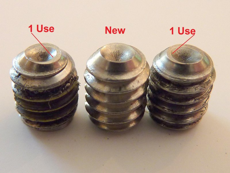
What is a one time use? If you tighten the set screw to torque once, that is your use. For example if you are installing the PSS and adjust it, tighten the set screw then realize the adjustment was wrong you now need to use a NEW set screw. If you look closely you can see how the used screws flatten. They will not score the shaft, like when new and sharp, to lock the rotor in place with a second use.
If you are in an absolute emergency you can swap the screw that had been the top "locking" screw for the bottom one, but this is still not advised as a regular practice. PYI recommend using new set screws with each tightening and loosening of the set screws.
PYI is glad to ship them out to you for a very minimal charge. Please, for your own good, DO NOT RE-USE set screws.
09-MAR-04
Clamp Collar
What is a clamp collar? Cheap Insurance. I am one of those cautious types and discovered these late one night on the McMaster-Carr web site.
I place it right behind the rotor and tighten it into place. I have been using them now for just about 9 years and consider them a very, very reasonably priced fail safe or insurance policy on the set screws I just discussed.
Interestingly enough I have been talking with PYI about clamp collars for a while now, and using them for about 9 years. PSS will be soon launching their own version of this. They claim they will be making their own product in-house as they feel they can control the quality better. According to an inside source they are reported to hold over 1000 pounds of force on a 1" shaft. That, is very good insurance.
09-MAR-04
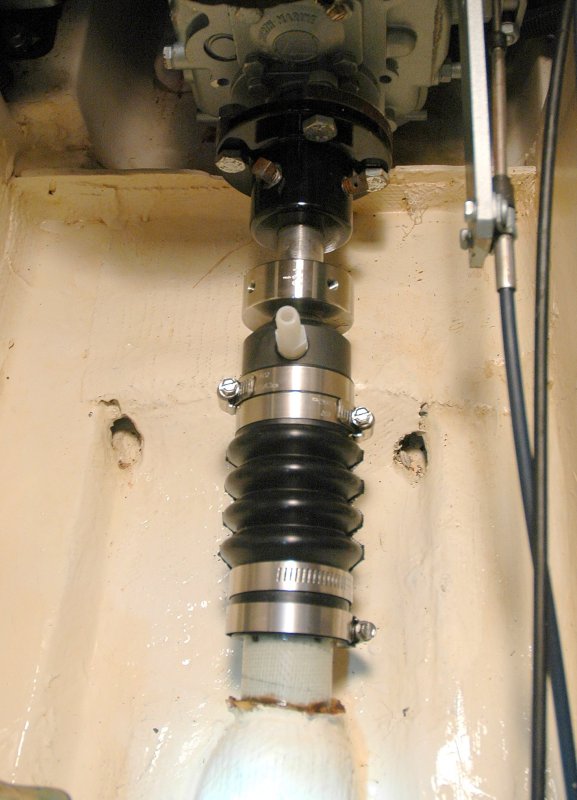
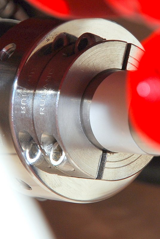
Clamp Colar Installed
This is a photo of the clamp collar in use on a v-drive installation.
09-MAR-04
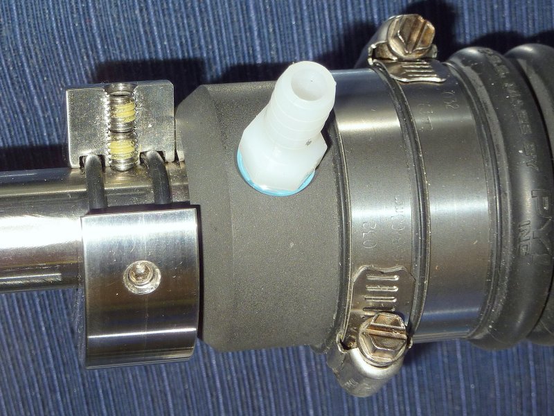
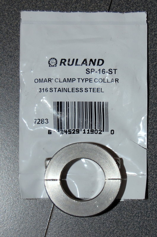
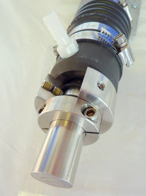
The Ruland Clamp Collar
Here's a better view of a Ruland clamp collar I buy from Mcmaster Carr. I brought this one to my friends shop where he has a PSS display to show more accurately how I use it. As of my last edit of this article PSS still did not have their clamp collar on the market.
*******CLICK BELOW FOR PAGE 2*******