17-DEC-2010
After Cutlass Removed
I get lots of comments to the effect that I make these jobs look too easy. They are easy. It does not mean they don't get frustrating though! I wanted to use this post to assure readers that I face the same obstacles as everyone when working on sail boats. This post is how boat jobs often go with one problem leading to or unmasking yet another. I call it the snowball effect.
This job was to be a simple shaft, cutlass, coupling & prop replacement but oh how things change when you get going. The boat, a mid eighties Ericson 34, has relatively low engine hours for her age but exhibited a very high level of vibration.
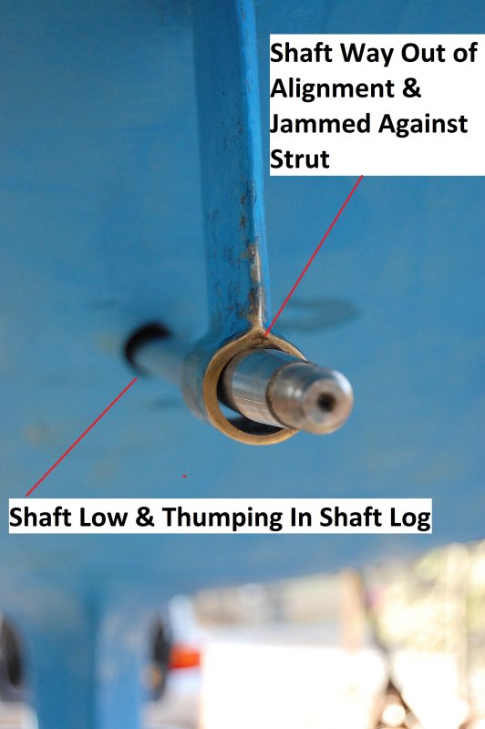
After I pressed out the cutlass bearing it became very apparent just how badly the vessel was misaligned.
Not only was the engine sitting far to low in the shaft log, and the shaft was thumping it when the engine was in gear, but it was also not passing through either the shaft log or the cutlass even close to parallel. The minute the cutlass came out the shaft sprang up and into the top of the strut. While boats can lose some alignment out of water it is usually in the order of thousandths of an inch when measured at the shaft coupling. My own CS looses about .001" from in water to out in terms of alignment and she has a longer shaft. This boat has a fairly short shaft and robust engine bed area so flex was clearly not causing this level of alignment issues. Read on and you'll find out the real reason this motor was so badly aligned.
17-DEC-2010
Failure Mode #1
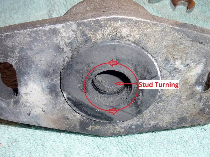
When we got the new shaft in place I wanted to adjust the engine first to do a rough alignment. Ericson, in all their infinite engineering wisdom chose a three point motor mount system for the Universal M-25 diesel. Three mounts is not the norm in boat building and almost all engine manufacturers ship engines with four mounts, generally with good reason.
The minute I put a wrench to the front mount in order to adjust it and thus drop the shaft from impinging on the top of the strut, the mount stud simply began to spin in the mount. In the marine environment the studs can get rusty or in this case the threads also get mashed and the stud with this type of design breaks free from the rubber it was molded into. Bad design for boats in my humble opinion. It was clear quite quickly the boat needed at least one new mount but I advised the owner to order three new ones and gave him the part numbers.
01-JAN-2011
Failure Mode #2
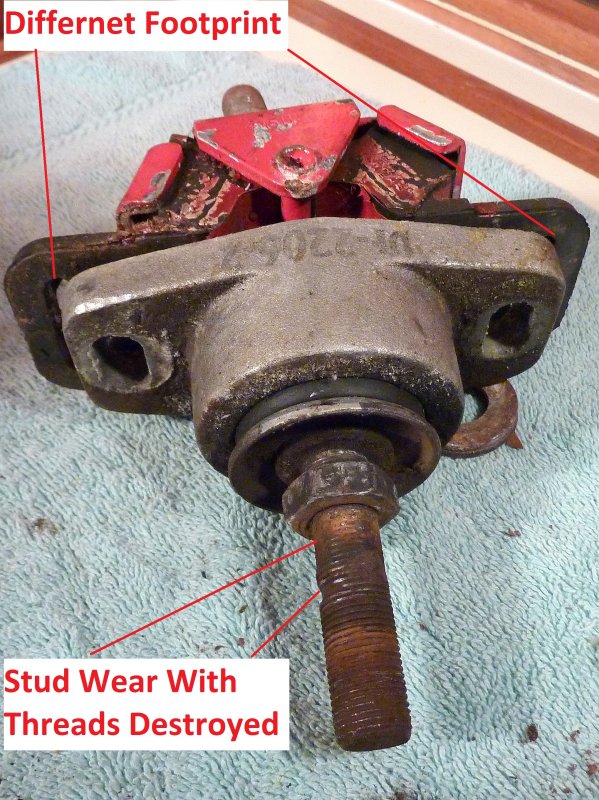
One thing I often see that destroys motor mounts prematurely is the lack of properly tightening the stud nuts that clamp the motor mount bracket. If these nuts are allowed to become loose the motor mount bracket or bell housing ears will vibrate over the threads and wear them away to nothing. All three of the mounts on this Ericson 34 had badly worn threads.
Worn threads will prevent any future re-alignment and require new mounts whether the rubber is ready to be replaced or not. One of the mounts was still in operable condition had the threads not been destroyed by letting the nuts come loose. The other two were toast and both spinning in the rubber.
In order to replace these mounts with a different model or brand would have entailed a far more costly and time consuming job due to differing bolt centers for the mounts. The three point design of the Ericson motor configuration is likely dependent on the rather stiff lateral design of these mounts. It was decided, though not happily, to re-place these mounts with the same brand & model.
31-DEC-2010
Failure Mode #3
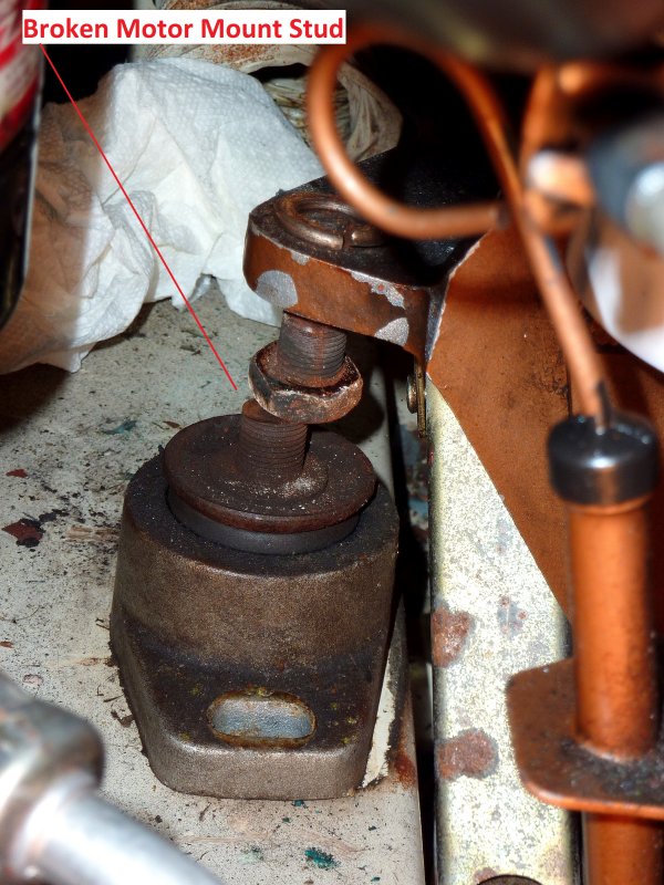
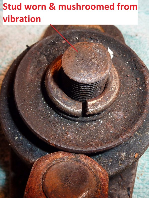
Yes, this simple shaft & cutlass replacement turned into a total comedy of errors. This was the starboard rear mount. It had been broken for quite some time as evidenced by the mushrooming of the sheared stud. With one failed mount, in a three point Ericson design you are now left with just two mounts holding a 350+ pound engine in place, scary stuff.
If there had been four mounts and one broke not as big a deal, you'd be back to what Ericson used every day, but with just three motor mounts...well... it is what it is.
31-DEC-2010
Sheared Motor Mount
This was the sheared stud. It had obviously been broken for a while as evidenced by the mushrooming of the stud. Broken mounts are not all that uncommon in Maine as we have lots of lobster traps to snag a motor and stall it by stopping the prop.
Sometimes the shaft bends, sometimes the prop, sometimes the gear box fails and sometimes a mount fails. I can't say what caused this mount to shear but I can say having only two mounts left, when one fails, is a little scary.
01-JAN-2011
Motor Mounts
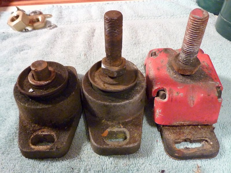
The red mount on the right is an older style Westerbeke/Universal engines factory motor mount. They are well designed, robust and do a very good job of isolating vibrations despite their rather expensive price tag. That red one has 2782 hours on it and the two failed mounts to the left are low hour mounts that had already been replaced once before. There are features of the Westerbeke/Universal mount that make them well worth the money:
1) You can not twist the stud inside the mount because it is welded directly to the mount cap.
2) The feet are encapsulated in molded rubber helping minimize noise and vibration transmission.
3) The metal cap prevents engine oils from eating away at the rubber by shielding it.
In short I am not a big fan of the two mounts to the left and I have seen the same type of failures repeated prematurely a number of times.
03-DEC-2010
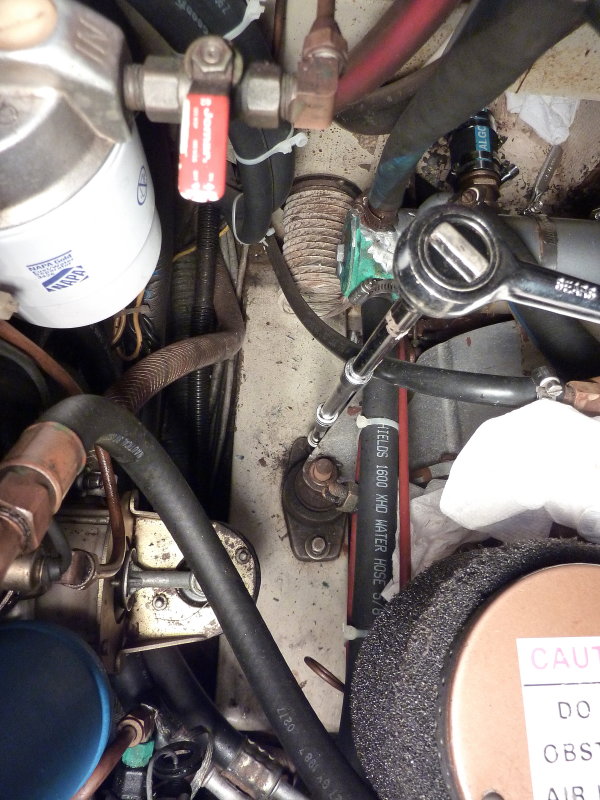
Oh & Failed Hose Clamps Too..
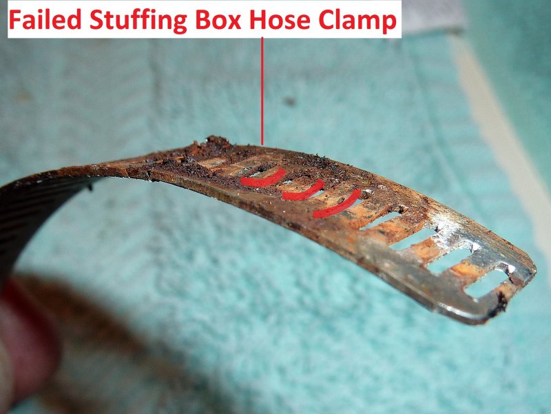
I'm not kidding, and yes it just keeps getting better, or worse depending upon how you look at it. This picture is one darn good reason why I detest "Ideal" style or perforated hose clamps. This was the hose clamp for the stuffing box hose. Two out of the four literally fell apart the minute I touched the screw driver to them.
Because the perforations make the center of the clamp softer than the edges, due to the removed metal for the perforations, they can bend upwards and away from the screw threads over time. The screw on this one literally fell out of the holder and yes, they were marked "all stainless". These hose clamps were keeping this boat afloat and thank God there were four.
Please consider the use of non-perforated hose clamps for your below water connections. I prefer the AWAB brand and have never once had one fail and I have seen buckets full of the perforated style fail.
31-DEC-2010
Finally Replacing A Mount
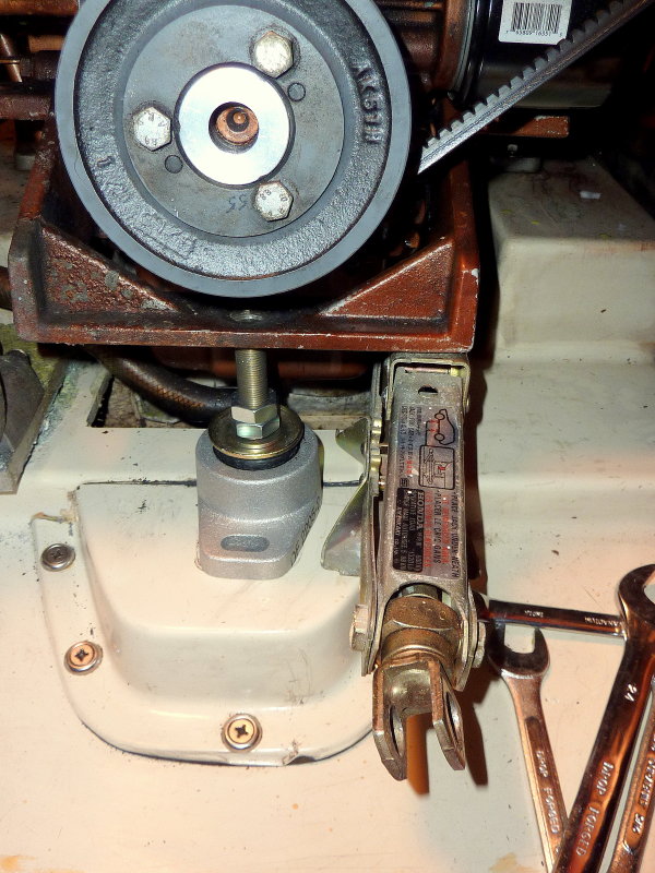
Whew, finally getting to the actual replacement of the mounts which is actually quite easy. To make this task easier I use my favorite scissor jack. This jack came from a Honda CRX I owned in high school. I loved it so much I kept it when I sold the car. This little jack folds to about 2" tall making it easy to slide under even the lowest motors. These can be found in junk yards and will be the best $5.00 you ever spent.
There was yet one more problem with this installation the stud on this front mount winds up behind the lower crank shaft pulley. When the boat is put in gear and the motor moves slightly forward under load the studs threads grind on the back of the pulley. In order to prevent this the stud needs to be cut shorter to clear the pulley once the engine is in alignment.
When jacking a motor be sure that any hoses, refrigeration belts or other items that can impede the raising of the motor are disconnected. You'll also want to loosen but not totally remove the top nuts on the other mounts to facilitate the motor being lifted enough to get the mount out. Removing the old mount and sliding this new one in place took all of about 10 minutes.
31-DEC-2010
Extensions Help
This engine room has very tight access on the starboard side. In order to remove the motor mount lag bolts I used multiple socket extensions, which made this a quicker and easier job.
31-DEC-2010
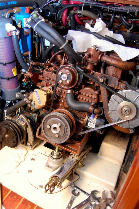
Cramped Engine Room
For a 34 foot sailboat this engine room is quite loaded with gear. She has Sea Frost engine driven refrigeration, fuel filters, water heater hoses, upgraded alternator and many other non-standard features that make working in there tight. The small jack is critical on engines like this for replacing motor mounts.
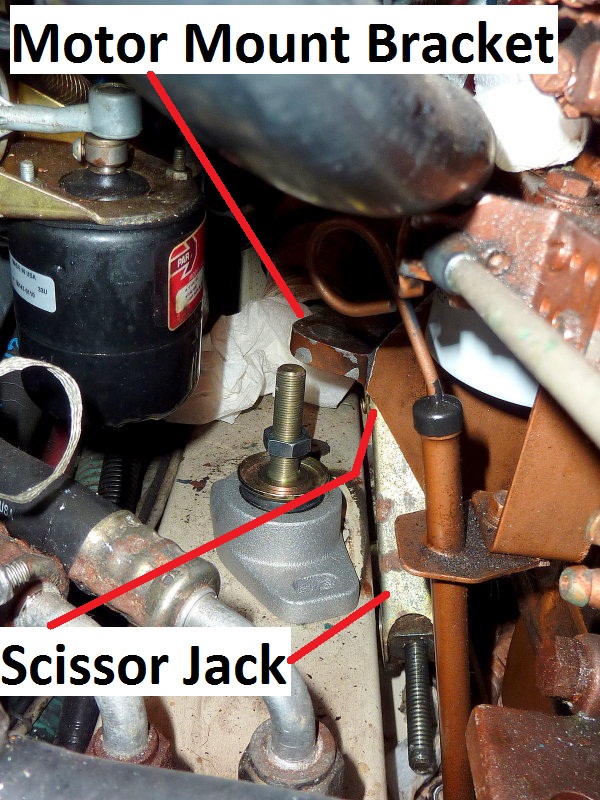
Replacing The Starboard Rear Mount
The camera angle makes this area look a lot more roomy than it really is. The scissor jack fits nicely between the engine bed stringer and the engine and is lifting in-board of the motor mount hole but using the motor mount bracket to jack the engine. This is a good illustration of why this little jack has stayed in my tool quiver since 1985..
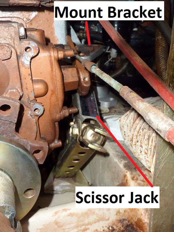
Same Mount Looking Towards The Bow
Here is another shot of the scissor jack. I collapsed it entirely and slid it in through the transmission opening in the bulkhead. You need to be careful and use mirrors to make sure you are not jacking on the oil pan or any sending units, hoses or fragile brackets. Oil pans can be used on small engines but I would advise using a block of wood to spread the load. If your oil pan is rusty please do not use it or you may punch through. If possible always use the mount or another strongly supported area of the engine.
Lifting one corner of an engine is not a lot of weight. The weight is so little that I can usually twist the jack screw by hand with no extensions or tools. With the other mounts loose it is very easy to lift one out. If you can get a good jacking angle and find enough support you can lift in the center and raise the front or rear and do two front or rear mounts at the same time.