If you decide on LFP then as I mentioned it is best designed as a system and a good alternator design and installation should always be part of that system.
Due to the extremely low internal resistance of these batteries, and the extremely flat voltage curve, LFP banks will tax an alternator to death if not properly installed. Because of the very low resistance the alternator will be in BULK mode for the vast majority of the charge cycle, (depends upon size) before even attaining absorption voltage.
With a high current alternator on lead acid, you can hit limiting/absorption voltage as low as 50% SOC where the alternator begins to catch a break.... You will not do this with an LFP, and your alternator will NOT get a break.
If you cycle the LFP bank to 80% DOD this means you are in BULK mode for approx 75% or more of the capacity of the entire bank bank before any sort of voltage limiting even begins..
BULK CHARGE means the alternator has not brought the terminal voltage of the battery bank up to ABSORPTION or the limiting voltage. In BULK the alternator is working FLAT OUT in what is referred to as CC or constant current mode... Once the bank comes up to ABSORPTION VOLTAGE we switch to CV or constant voltage mode where voltage is held steady and current begins to taper off based on what the battery can accept at that SOC and voltage.
In BULK / CC the alternators capacity/ability is your limit.
In ABSORPTION / CV the battery determines how much current can flow at a specific SOC and terminal voltage
Take a 400Ah LFP bank at 80% DOD and that is 320Ah's that need to go back in. With a 130A alt running hot at about 100A this means BULK will be about three hours! There is no alternator on the planet that can run at full bore for three straight hours, into an LFP bank, inside the typical engine room on a boat, unless perhaps the diode rack has been mounted externally with its own cooling fan. There is not a single small case alt that will survive this for long without a proper installation. NONE!!!
Let's say you're a marathon runner, and you can do the 26 miles at a pretty good jog. This is similar to a high capacity alternator feeding a large lead acid bank. You start out strong (BULK/CC) but as the race goes on you plateau & settle in at a sustainable pace (ABSORPTION/CV).
An alternator feeding an LFP bank is like trying to SPRINT the entire 26 mile marathon. Not going to happen....
FACTORY ALTERNATORS:
Some factory alternators have a built in temp compensation and it resides in the voltage regulator to reduce current / voltage as the alternator heats up. This really defeats the purpose of "charging fast" or even having an LFP bank if you want to capitalize on the fast & efficient charging LFP batteries can offer.. While this alternator temp compensation feature is self protective of the alternator it is really a very poor regulation choice for an LFP bank. I have seen Hitachi alternators so hot they have reduced the voltage output to 13.2V. Considering the resting voltage of an LFP bank is higher that, well..... Do it right and build this as a "system"..
High Performance Alternators:
With LFP you must ignore the bovine dung ratings manufacturers suggest. Kost "high performance" alternators are rated based on stator/rotor specification/design size. They are NOT rated for continuous duty at full output! What? Bottom line is DO NOT EVER expect the "rated output" from your high performance marine alternator for more than a few minutes. Depending upon the specific alternator plan to reduce your actual constant duty output by as much as 20-50% or more.
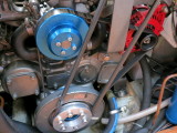
PHOTO:
Here we are looking at a Yanmar four cylinder engine with a Balmar / Alt Mount serpentine conversion and a Balmar AT series 165A alternator. The Balmar AT series is a hairpin wound small case alternator. This stator / rotor design is relatively new technology for the marine market and allows extremely high performance out of a small case alternator.
Currently the Balmar AT series are the meanest, bad a$$ small case alternators you can buy, performance wise, but they are still a small case alt and LFP can still over-tax them and burn them up if they not set up correctly.. I used the $$ signs in the word ass for a reason, they are not inexpensive...
Another great option, if you are locked into a small case alternator, is to let Mark Grasser DC Power Solutions (LINK) build you a remotely rectified small case alternator. This is what I run on my own vessel and Mark is a great guy to deal with.
Unfortunately many sailboats don't have the room for a massive large case alternator with external bracket etc. If you do, that is great, and I would steer you in that direction if not Mark Grasser or a Balmar AT series would be the best direction to go.
Does this mean other small case high performance alternators can't be used on LFP? Absolutely not, it just means the percentage of "rated output" you get out of the alternator will be less than it is on an AT series and it will need to be dialed back in the regulator settings further than an AT series will. While the AT is a great little alternator it is not immune to being cooked from improper set up and installation.
With a remotely rectified Mark Grasser alternator the remote rectifier removes a lot of heat from the alternator and allows it to run significantly cooler with higher continuous outputs. On my own vessel I do not use current limiting and the alternator has never been hotter 227 degrees. The same alternator before I converted it to remote rectification could easily exceed 275 degrees and alternator, before I converted it, required belt manager level 4 in terms of current limiting.