The battery monitor is a very useful tool for a boat-owner who has to survive on battery power. When properly installed, calibrated and monitored they can extend the life of a battery bank especially when used smartly.
Allow me to reinforce that:
WHEN PROPERLY INSTALLED - About 90% of Ah Counters I come across are NOT properly installed.
WHEN PROPERLY CALIBRATED - About 98% of Ah counters I come across are NOT properly calibrated/programmed.
When NOT properly installed and kept well calibrated they can be HORRIBLY inaccurate...
**This article is only half the story. Installation is important, but calibration is equally as important. For more on calibration please don't ignore the other article:
Rule #1 of most Ah counters: Disable the "auto-sync" feature and use manual "known full" re-sets.
What is known full?
*Voltage at 14.4V+ - Check
*Net "accepted current less than 1.5% of Ah capacity - Check
*Okay to reset to full
NOTE: Battery voltage should be at absorption level NOT a *float voltage.
If you have been at a dock at float voltage for multiple days then it is safe to assume you are full and a manual reset is fine. When out cruising use absorption voltage!
FACT: From the day you install your bank the physical capacity is ever changing.
The problem with traditional Ah or Coulomb counters is keeping them accurate. As batteries age their capacity changes, it is an ever moving target, so the 100Ah battery you bought three years ago may now only be a 75Ah battery.
If your battery monitor is still programmed for a 100 Ah capacity, and you are drawing to 50% of the assumed Ah capacity out of it, based on this 100Ah's, you are really now drawing the bank to just 25% SOC, rather than the well accepted safe discharge level of 50%.
Follow me on this one. You had 100Ah programmed into the Ah counter. Your battery, due to age and use, is now 75Ah's. You now draw 50% of 100Ah's out of the battery, except the battery is only now 75Ah's and you wind up at; 75Ah - 50Ah = 25Ah remaining or approx 25% SOC. Actually if you threw Peukert's exponent into the mix you may actually be lower or higher depending upon the actual load at which it was drawn. Holy cow this is confusing....! This is but one example where an Ah or Coulomb counter can become inaccurate. These devices are not "plug & play" and are only as smart as you the owner are. Please be aware of this.
Coulomb or Ah counters can count Ah's very, very accurately. However, they have NO CLUE about your banks physical Ah capacity. It is up to you, the owner, to tell it the bank capacity and program for this ACCURATELY.
A trick many of us in the industry use is to start with a lower programmed Ah capacity than the bank is rated for. So for the 100Ah battery I might initially program it at 95Ah's so the owner is never actually drawing to 50% SOC that first year (self protective feature). The next year I might remove another 3% off the capacity etc. etc.. These are just rough guesstimates and on many banks tend to correlate ok, but never perfect. I then also count on the fact the battery is being drawn at average currents that are below the rated load. This can lead to more bank capacity, but again this gets CONFUSING for the average boater to understand any time we bring our good friend Mr. Peukert into the equation.
The only way to accurately know your actual battery capacity is to perform a physical 20 hour load test. This is complicated, time consuming, and very few boaters are willing to do this. To be honest I don't know of a single boater who actually has conducted an accurate 20 hour load test. Ah / Coulomb counters rely on the actual 20 hour capacity figures being accurate, to actually remain accurate, over time. No accurate 20 hour capacity figure, no reasonable accuracy in the Ah counter, only a "close enough" range. This may not be half-bad but is a ways from accurate. Just be aware of this when you are assuming your Ah counter is accurate, in relation to YOUR bank.
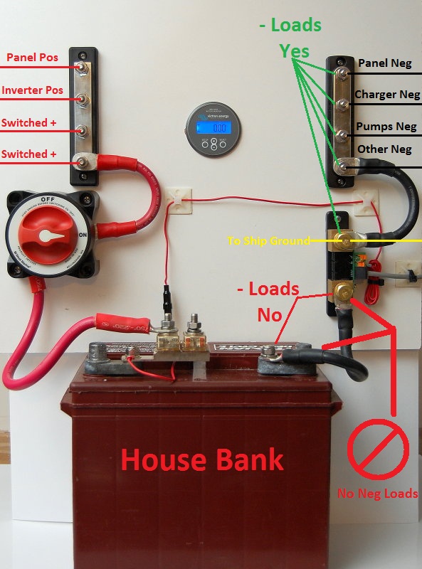
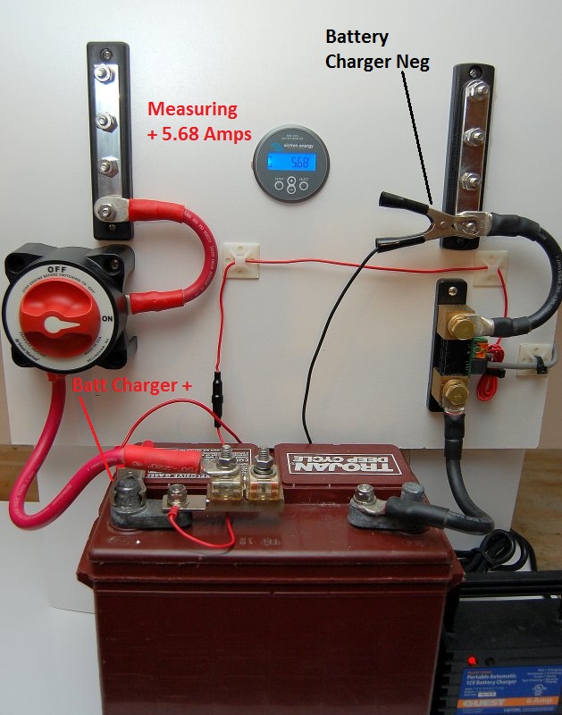
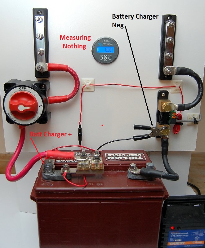
Unfortunately the scenario I laid out for a Coulomb/Ah counter is just one of the many ways these devices can become tripped up and lead to inaccurate SOC readings. There are many more "gotcha" scenarios that can rear their ugly head. These include shunt wiring mistakes, battery temperature, false re-synchs caused by solar or wind, changes in physical Ah capacity, changes in charge efficiency as the battery ages, incorrect programing etc. etc..
For the last 20+ years however, these are all we've had. They are certainly better than nothing at all!
Despite all the areas Ah counters can get tripped up I suspect the big reason they lead to longer bank life is simply because they make owners more aware of their bank. More awareness of your bank and charge source performance is important. More awareness can play a larger role than we may otherwise assume.
For years I have been trouble shooting and helping owners try to use these devices in a smarter and more accurate manner. Unfortunately it often feels as though I beat the drum inside a sound proof room and no one can hear it. When owners understand how an Ah counter works, they can be very useful. Most all of my customers have had longer battery life as a result.
With new battery technologies costing three to ten times what wet cell technology does and many boaters moving to newer technologies such as GEL, AGM, TPPL AGM and LiFePO4 Li batteries, accurate or as accurate as possible monitoring, of an expensive bank, is almost a prerequisite.
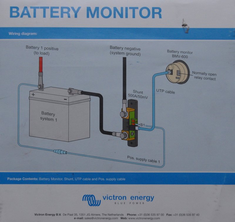
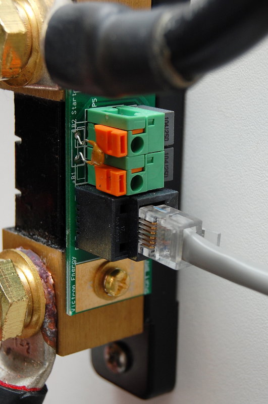
People often ask me questions about how to install a battery monitor so I took some time and tried to make it simple. They are actually easy to install but there are a couple of "gotcha" traps that you may find your self falling victim to.
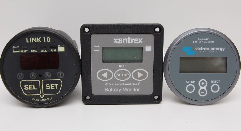
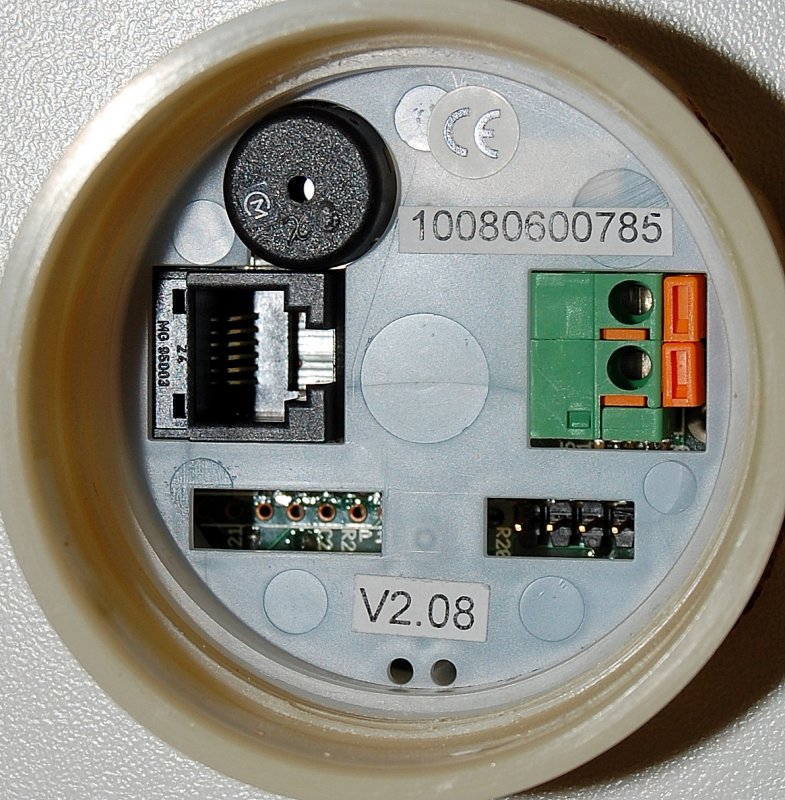
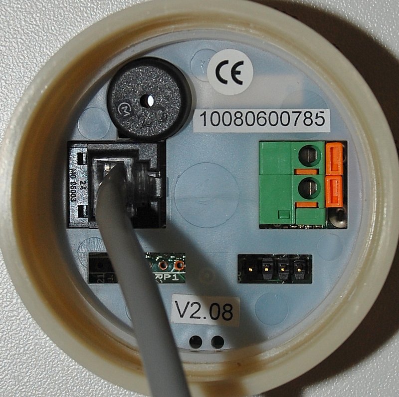
There are a fair number of Ah counting battey monitors on the market. Blue Sea Systems, Xantrex, BEP, Victron, NASA, Philippi and a few others make them. Currently the Victron units are the easiest to install and also the least expensive, making them a good value in an Ah counter..
Personally I believe the majority of boaters would be better off with the new Balmar Smart Gauge Battery Monitoring Unit, rather than trying to keep a traditional Ah counter accurate..
Smart Gauge Battery Monitoring Unit (LINK)
I currently use a Xantrex Link-Pro on my own boat but all Ah/Coulomb counters all do basically the same thing, count Ah's.. I would much rather use a Balmar Smart Gauge on my own boat, but the Smart Gauge simply does not work with Lithium batteries, and I have a LiFePO4 bank. The Victron however is a significantly better deal than the Xantrex so if you want an Ah counter this is the one that is the best value..