


|
|
|
|
|
|
| |
NOTE: Please click any image to make it larger.
The topic of wiring a high performance alternator regulator, and doing it correctly, comes up a lot. One of the most misunderstood areas, that can bite into your charge performance, is incorrect voltage sensing. This short article deals only with correct voltage sense wiring for the Balmar MC or ARS regulators as well as the Xantrex XAR (made by Balmar).
With a high performance voltage regulator, such as the older Balmar MC-612 or current MC-614, and some others, they include a dedicated voltage sensing circuit. This is a great feature, if you wire it correctly..
NOTE: The Balmar ARS-5 and Xantrex XAR regulators do not have a dedicated positive volt sensing lead. On these models voltage sensing is done between regulator B+ (red) and regulator B- (black). If these wire runs are extended to the battery bank care must be taken to account for the voltage drop in the red wire which can carry as much as 6A +/- to drive the field current. For the best performance you'll want voltage drop in the regulator B+ wire to be as close to zero as possible. If you've not already purchased a regulator, then consider the Balmar MC-614..
A voltage sensing circuit is a circuit intended to carry minimal to no current so there is minimal voltage drop in this measurement circuit. The voltage sensing circuit should really be considered a voltage correction circuit or a voltage drop compensation circuit.
The voltage sensing circuit works by utilizing these smaller sensing wires in order to compensate for the voltage drop in the larger alternator output wires.
The larger alternator positive & negative B+ & B- cables are actually carrying the high alternator output current, and even if very large, they will suffer from some voltage drop. Voltage sensing is supplied on these high performance alternator regulators so we can achieve the correct regulator set point voltage, at the battery itself, not just at the back of the alternator. These sensing wires measure the actual battery terminal voltage and allow the regulator to drive the voltage at the battery end to the correct point.
Voltage is the pressure that allows current to flow into the batteries. Incorrect voltage sensing causes your regulator to prematurely begin limiting voltage. Once voltage is held steady current has to decline in order to not over shoot the voltage limit of the regulator. The issues of voltage drop and incorrect voltage sensing leads to longer charge times. Sail boats, more so than power boats, simply want to pack as much energy back into the bank and do so in the shortest time possible. If you have incorrect sensing this can rather dramatically cut into how much capacity you can return in a given period of time.
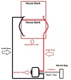
The voltage drop numbers seen in these three illustrations are the actual voltage drops measured on a boat I worked on two years ago. The alternator output wires, both positive and negative, according to the owner, were sized for a 3% +/- voltage drop. However terminations, fuses etc. were not accounted for in the voltage drop calculation and the length wound up a bit longer than anticipated in the owners original calculations.
In this illustration we have the alternator regulator prematurely limiting voltage to 14.4V because it is sensing the voltage BEFORE THE VOLTAGE DROP OCCURS.. The alternator volt sense circuit is seeing 14.4V, at the alternator, and the regulator is now limiting or holding the voltage steady at 14.4V. Now take a look at what is going on at the battery end. At the battery end the voltage is just 13.79V and considerably less current can flow into the bank at 13.79V than it can at 14.4V.
If you are buying a high performance alternator and regulator some of your performance improvements come from the alternator no longer being what is referred to as "self sensed". Part of the performance improvements, when moving to external regulation, come from the ability to directly sense the battery terminals, instead of the back of the alternator.
"But RC it's only a 3% voltage drop?"
While 3% sounds good, 3% on a voltage limit of 14.4V = 0.43V drop. This wire drop is on top of any terminations or fuses these wires pass through on the way to the bank. The net result is an alternator regulator limiting voltage to 14.4V and the batteries seeing just 13.97V. That .4V makes a big difference in how much current your batteries can take at XX SOC...
"But RC as current declines, when the battery approaches full, there will be little to no voltage drop. The batteries will eventually get to target voltage, so what's the big deal?"
Yes, this thinking is in-fact correct. However there are a few issues with it.
#1 Yes, voltage drop is directly related to the current flowing through the wires. In an ideal world we'd have all the time we'd want, or need, to charge the batteries. With cruising boats we simply don't have this time or the luxury of *6 to *12+ hours to do this (*battery type and state of health dependent). For the reasons of time alone voltage drops, in system wiring, cut into the charge speed of the high performance system you just paid buku bucks for.
#2 Once the regulator attains the 14.4V - 14.8V absorption voltage limit the time clock or cycle algorithms begin running on the absorption cycle. Batteries need a good absorption charge cycle for optimal health. If the regulator is dropping to float just about the time the batteries physically come up to 14.4V - 14.8V (depends upon your batteries where this limit will be), due to the incorrect voltage sensing issue, we really get a short and poor absorption cycle despite the regulator thinking they did. This, compounded on the many other charging problems I see, can lead to chronic undercharging. An inadequate absorption cycle can result in the effects of sulfation setting in sooner than it should.. With voltage drop the regulator has been in what it thinks is absorption for longer than the batteries have. Think about this....
Incorrect placement of the voltage sensing wires is easy to address and fix with external regulation.
Don't let your regulator enter absorption before your batteries get there!!
© All Images property of Compass Marine Inc.