


|
|
|
|
|
|
| fred harmon | profile | all galleries >> Galleries >> ipod | tree view | thumbnails | slideshow |
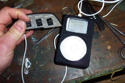
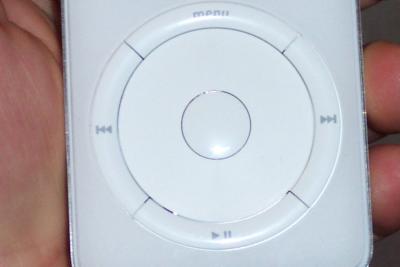 Ipod controls |
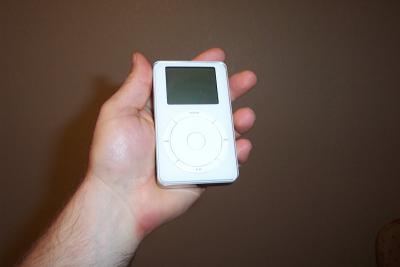 Small, sleek and sexy |
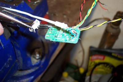
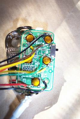 Here is a view of the circuit card for the remote with my wires tacked on |
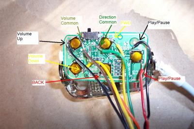 This shows the wires and signals for the remotes switches |
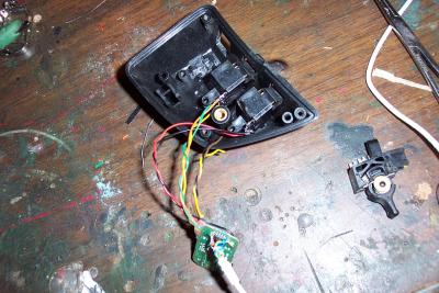
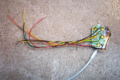 A view of the whole assembly with wires added |
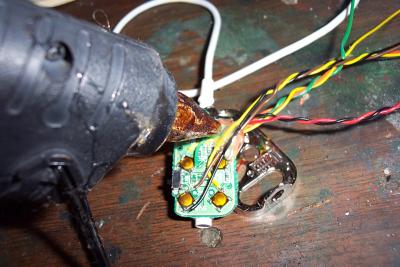 A few drops of hot melt glue provide strain releif for the wires so I don't break the solder joints. |
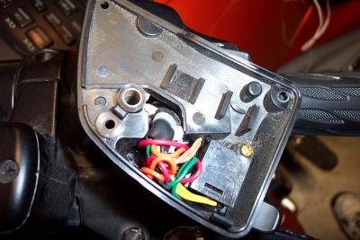
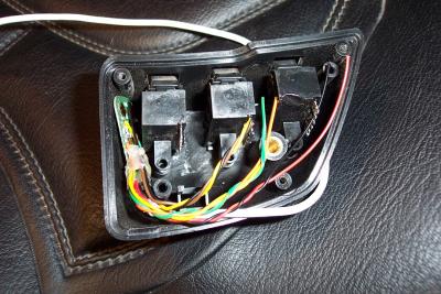
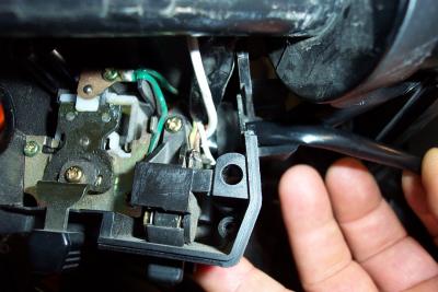
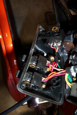 Here is a look inside the switch housing of the CB controls |
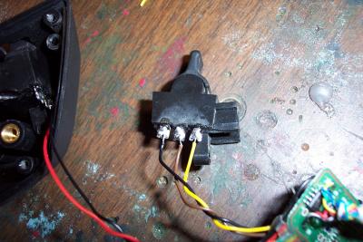
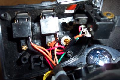 Here I have one switch free with CB wires still connected |
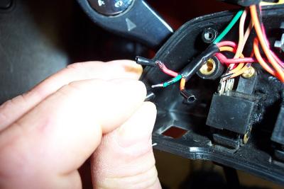 I carefully unsolder each CB wire and cap it with heat shrink. |
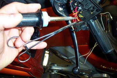 A hemostat works as a third hand for unsoldering wires from switches |
 Next I tucked all the unused CB wire ends down and out of the way into the housing |
 I unsoldered and removed the headphone connector to make the circuit card thinner and easier to fit into the housing |
 Note circuit card positioned on left side and wires cut to length |
 Now I begin soldering wires onto switches |
 This is the volume switch |
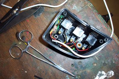 Here all switches are soldered and wires routed inside housing. |
 Before I go any further I test to make sure they all work properly |
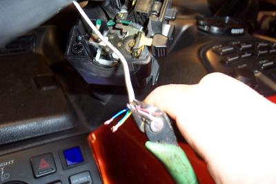
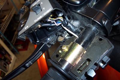
 I had to cut the remote wire to route it and lengthen it. |
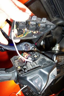 I routed the wire down to the bottom side of the grip assy |
 Remote wire comes out bottom of CB switch housing. |
 I cut off the Red, White, and Black audio wires on this end of the remote cable, as I won't need them |
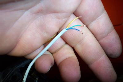 Only the three serial data wires are needed to go all the way to the remote circuit card in the switch housing |
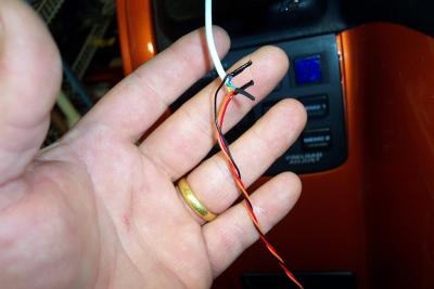 I had to splice in a three foot length of wire for the three serial data wires as the remote cable wasn't quite long enough. |
 I put heat shink over a section to hide the white cable and protect my splice |
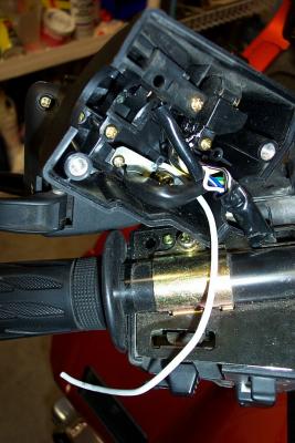
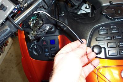
 Remote cable routed out bottom of left hand grip assy. |
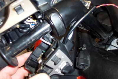 Here is the wire being routed and grip assy installation |
 Here the bottom half of the grip is installed with wire routed |
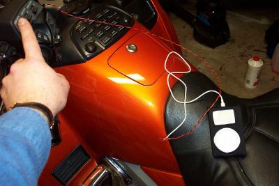 All back together and testing once more before I make the final installation |
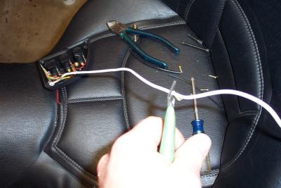
 Installing wires in handlebar harness |
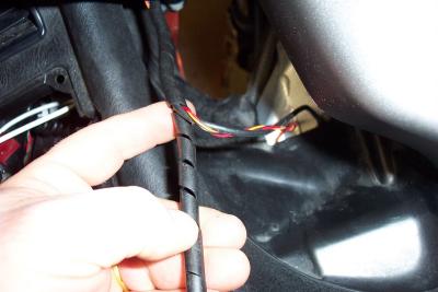 I wraped wire loom around the exposed portion of the section of wires I added |
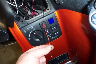 I routed the three serial wires out by the glove box and then spliced them back to the other end of the remote cable |
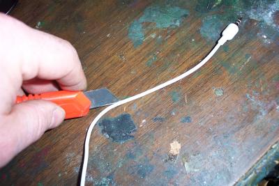 Here I carefully sliced open the sheath on the remote cable to extract the audio wires |
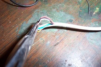 Three audio wires pulled out of cable (red, white, & black) |
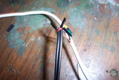 I spliced the audio wires into a seperate female mini plug connector. Red is GROUND, Black is LEFT and WHITE is RIGHT channel. |
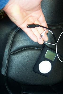 Here is the final cable with added female mini plug |
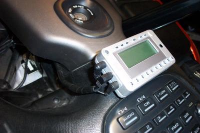
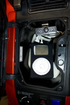 Ipod in it's new home all hooked up |
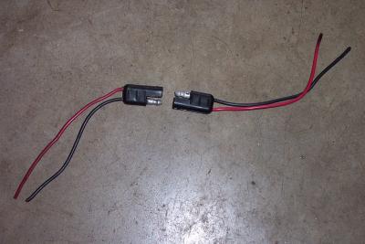 Here are the Radio Shack power connectors I use on the bike |
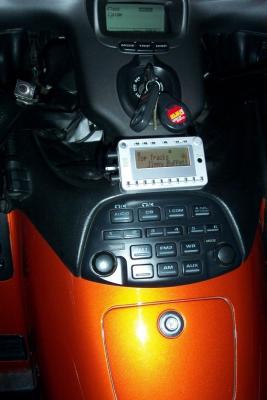 XM radio installed on top shelter, held in place with industrial velcro |
 I routed the wires down and out of sight inside the the instrument cover |
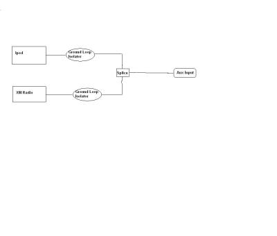 Ipod and XM wiring diagram through Ground Loop isolators |