


|
|
|
|
|
|
| fred harmon | profile | all galleries >> Galleries >> G Force Alarm System | tree view | thumbnails | slideshow |
| previous page | pages 1 2 3 ALL | next page |
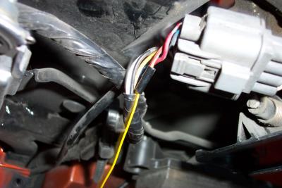
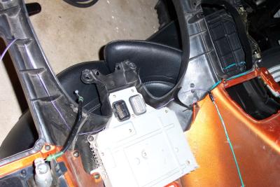
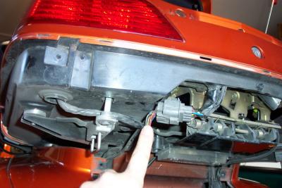 Remove the lower trunk panel to access the trunk switch sense wire in connector C16 |
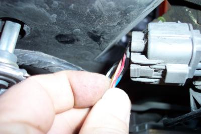 The wire you need to attach to is the brown wire with a red stripe (see page 11-1 of the ETM) |
 You can attach a piggy back connector to this wire and no splicing will be needed |
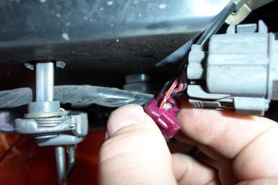
 Piggyback connector in place |
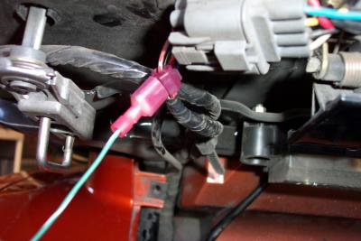
 Or, you can solder and heat shrink the new wire to the existing brown/red wire as I did |
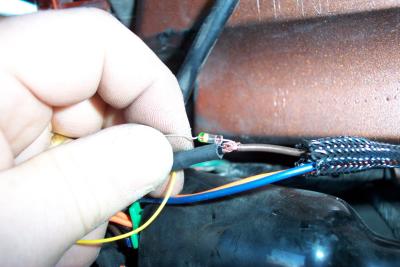 The other end of your new wire needs to be attached to a diode, and then connected to the brown wire in the alarm harness |
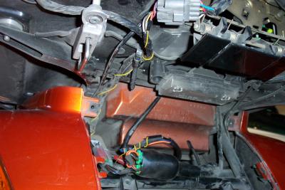 Wire in place and connected to alarm and trunk sense switch |
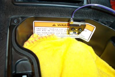
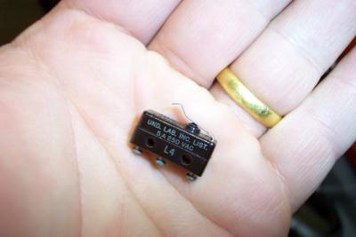 Here is a micro-switch I used to make a sense switch for the rear gloveboxes. You could also use a magnetic switch |
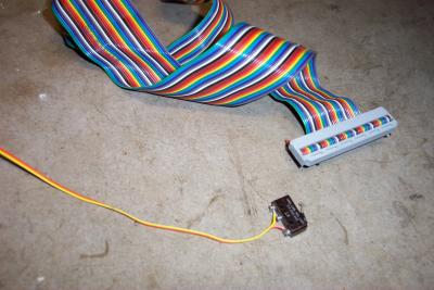 I soldered two strands of ribbon cable to the normally closed switch contacts |
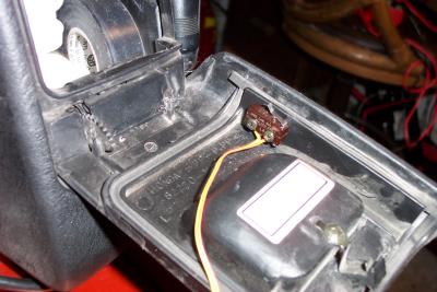 One option is to attach the switch to the sides of the door. |
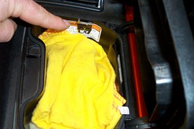
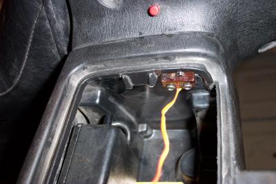 I decided to install it with the switch attached to the top edge of the glove box |
 Here is the switch fully installed |
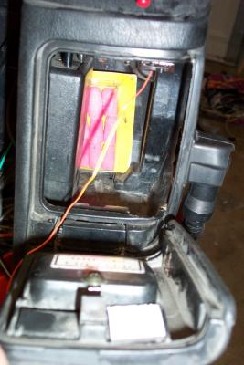
 I also installed micro-switches in both front gloveboxes. |
 I made a small hole and ran the wires out the back of the glovebox and through a small 2 pin connector |
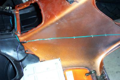 I removed the top shelter and routed the wires down the inside of it, tacking them in place with some hot melt glue |
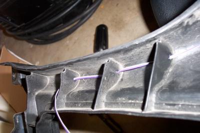 I melted holes in the bottom of the top shelter guides with a hot nail and routed the wires through to hold them in place |
 Completed wire installation. All 4 switch wires then go to ground on one side and to brown wire in alarm harness on other side |
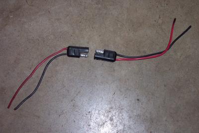 Here are the Radio Shack power connectors I use on the bike |
| previous page | pages 1 2 3 ALL | next page |